Asymmetric boost unit based cascaded boost converter

A boost converter, asymmetric technology, applied in the direction of output power conversion device, DC power input conversion to DC power output, instruments, etc., can solve the problems of high voltage gain, low efficiency, unrealizable, etc., and achieve reduction Requirements for the number of components, the effect of superior boost performance

Inactive Publication Date: 2018-05-01
SOUTHEAST UNIV
View PDF5 Cites 10 Cited by
  • Summary
  • Abstract
  • Description
  • Claims
  • Application Information

AI Technical Summary

Problems solved by technology

However, in practical applications, due to the limitation of parasitic parameters, very high voltage gain cannot be achieved
If a cascaded topology is used, the problem of low efficiency caused by the increase in the number of devices will be highlighted again.

Method used


Image

  • Asymmetric boost unit based cascaded boost converter
  • Asymmetric boost unit based cascaded boost converter
  • Asymmetric boost unit based cascaded boost converter

Examples


Embodiment Construction

[0029] The technical solution of the present invention will be further introduced below in combination with specific implementation methods and accompanying drawings.

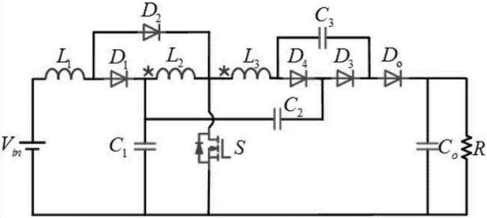
[0030] The first specific embodiment discloses a cascaded boost converter based on asymmetric boost units, such as figure 1 shown, including the input supply V in , input supply V in The positive connection of the inductance L 1 at one end, the inductance L 1 The other ends are connected to the freewheeling diode D 1 anode and freewheeling diode D 2 anode of the freewheeling diode D 1 The cathodes of the coupled inductors are respectively connected to the primary winding L of the coupled inductor 2 terminal of the same name, capacitor C 1 One end and the capacitor C 2 One end of the coupled inductor primary winding L 2 The opposite ends of the coupled inductors are respectively connected to the secondary winding L of the coupled inductor 3 The terminal with the same name, freewheeling diode D 2 The c...


PUM


Abstract

The invention discloses an asymmetric boost unit based cascaded boost converter. Primary and secondary windings are used repeatedly, and asymmetric boost units are fused, so that the boost capabilityof the converter is improved greatly; two capacitors and one diode form a novel clamp circuit, energy of a leakage inductor is absorbed effectively, and the efficiency of the converter is improved; and the two capacitors are connected in series to reduce the voltage stress of an output rectifier diode effectively. Three diodes realize zero-current ON, and one diode realizes zero-current OFF.

Description

technical field [0001] The invention relates to a boost converter, in particular to a cascaded boost converter based on an asymmetric boost unit. Background technique [0002] With the depletion of traditional fossil energy and the deteriorating environment of human beings, the development of clean renewable energy is imminent. All countries in the world are committed to the research and development of new energy applications, of which solar energy and wind energy have been obtained a wider range of applications. However, for these systems, how to operate grid-connected and meet the high voltage requirements in the grid is still the most important issue. At present, a large number of boost converters have been developed to meet these applications. Among different converters, the traditional BOOST converter can theoretically increase the voltage gain by increasing the duty cycle. However, in practical applications, due to the limitation of parasitic parameters, very high vo...

Claims


Application Information

Patent Timeline
Patent Type & Authority Applications(China)
IPC IPC(8): H02M3/155
CPCH02M3/155H02M3/1552
Inventor 林明耀艾建乐伟李晖刘同民
Owner SOUTHEAST UNIV
Why Eureka
Try Eureka