Secondary DC-DC converter of asymmetrical voltage boosting unit of fuel cell system

A fuel cell system, DC-DC technology, applied in the field of boost converters, can solve the problems of unrealizable, high voltage gain, low efficiency, etc., and achieve the effect of improving efficiency, improving boosting capacity, and working efficiently

Inactive Publication Date: 2018-07-17
SOUTHEAST UNIV
View PDF1 Cites 2 Cited by
  • Summary
  • Abstract
  • Description
  • Claims
  • Application Information

AI Technical Summary

Problems solved by technology

However, in practical applications, due to the limitation of parasitic parameters, very high voltage gain cannot be achieved
If a cascaded topology is used, the problem of low efficiency caused by the increase in the number of devices will be highlighted again.

Method used


Image

  • Secondary DC-DC converter of asymmetrical voltage boosting unit of fuel cell system
  • Secondary DC-DC converter of asymmetrical voltage boosting unit of fuel cell system
  • Secondary DC-DC converter of asymmetrical voltage boosting unit of fuel cell system

Examples


Embodiment Construction

[0019] The technical solution of the present invention will be further introduced below in combination with specific implementation methods and accompanying drawings.

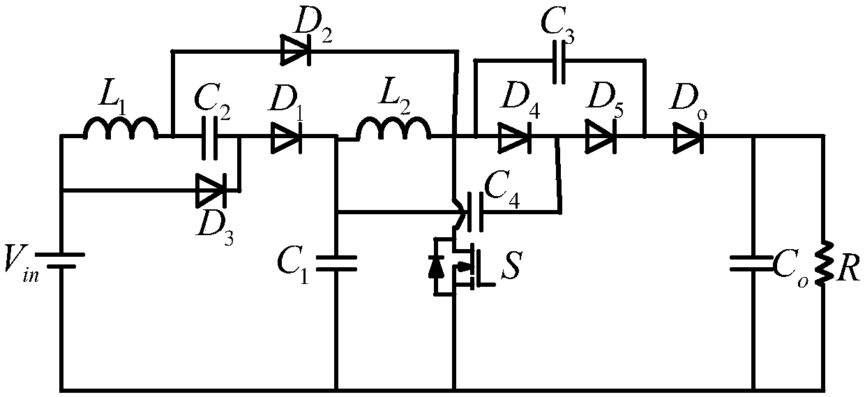
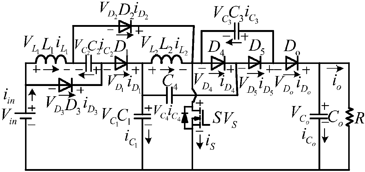
[0020] The specific embodiment of the present invention discloses a secondary DC-DC converter of an asymmetric boost unit for a fuel cell system, such as figure 1 shown, including the input supply V in , input supply V in The positive connection of the inductance L 1 One end of the freewheeling diode D 3 the anode, the inductor L 1 The other ends are connected to the freewheeling diode D 2 anode and capacitor C 2 One end of the capacitor C 2 The other ends are connected to the freewheeling diode D 1 anode and freewheeling diode D 3 the cathode of the freewheeling diode D 1 The cathodes are respectively connected to the inductor L 2 One end of the capacitor C 1 One end and the capacitor C 4 at one end, the inductance L 2 The other ends are connected to the freewheeling diode D 4 The anode, capacito...


PUM


Abstract

The invention discloses a secondary DC-DC converter of an asymmetrical voltage boosting unit of a fuel cell system. The converter comprises an input power supply V<in>; the positive electrode of the input power supply V<in> is connected with one end of an inductor L1 and the positive electrode of a fly-wheel diode D3; the other end of the inductor L1 is connected with the positive electrode of a fly-wheel diode D2 and one end of a capacitor C2 separately; the other end of the capacitor C2 is connected with the positive electrode of a fly-wheel diode D1 and the negative electrode of the fly-wheel diode D3 separately; the negative electrode of the fly-wheel diode D1 is connected with one end of an inductor L2, one end of a capacitor C1 and one end of a capacitor C4 separately; and the otherend of the inductor L2 is connected with the positive electrode of a fly-wheel diode D4, one end of a capacitor C3, the negative electrode of the fly-wheel diode D2 and the drain of a switching tube Sseparately.

Description

technical field [0001] The invention relates to a boost converter, in particular to a secondary DC-DC converter of an asymmetric boost unit for a fuel cell system. Background technique [0002] With the depletion of traditional fossil energy and the deteriorating environment of human beings, the development of clean renewable energy is imminent. All countries in the world are committed to the research and development of new energy applications, of which solar energy and wind energy have been obtained a wider range of applications. However, for these systems, how to operate grid-connected and meet the high voltage requirements in the grid is still the most important issue. At present, a large number of boost converters have been developed to meet these applications. Among different converters, the traditional BOOST converter can theoretically increase the voltage gain by increasing the duty cycle. However, in practical applications, due to the limitation of parasitic parame...

Claims


Application Information

Patent Timeline
Patent Type & Authority Applications(China)
IPC IPC(8): H02M3/07
CPCH02M3/07
Inventor 林明耀刘同民艾建
Owner SOUTHEAST UNIV
Why Eureka
Try Eureka