Automatic assembly machine of clamps

An automatic assembly machine and clip technology, applied in assembly machines, metal processing equipment, manufacturing tools, etc., can solve the problems of feeding seat wear, assembly failure, trouble, etc., and achieve the effect of improving accuracy, improving precision, and avoiding damage

Inactive Publication Date: 2018-05-04
浙江宏日自动化科技有限公司
View PDF2 Cites 44 Cited by
  • Summary
  • Abstract
  • Description
  • Claims
  • Application Information

AI Technical Summary

Problems solved by technology

[0005] Question 1: In this process, there is a critical moment, that is, when the hinge shaft reaches the discharge end, at this time, the second drive member controls the lead rod to advance toward the discharge end, and the lead rod rotates through the first hinge seat, the second hinge The seat and the spring are in conflict with the end of the hinge shaft with a groove to support the hinge shaft of the feed rod. Because the aperture of the feed channel is large, the horizontal position of the hinge shaft will deviate when the push rod pushes the hinge shaft. However, the hinge shaft needs to pass through the first hinge seat, the second hinge seat and the spring, which requires high accuracy for the alignment of the position. A slight deviation of the position will cause the hinge shaft to fail to insert into the first hinge seat. , the second hinge seat and the spring, the assembly failed
If the hole diameter of the feed channel is set smaller, the hinge shaft will not easily slide out under the action of friction, but the resistance to the push rod pushing the hinge shaft will be large, which is not conducive to the discharge of the hinge shaft
[0006] Question 2: The role of the lead rod is to guide the first hinged seat, the second hinged seat and the spring. The lead rod is connected to the third drive that controls the rotation of the lead rod. When the lead rod cannot be inserted into the first hinged seat accurately , the second hinged seat and the spring, the lead rod itself will be stuck, and when the lead rod is stuck, the third driver is still driving the lead rod to rotate, and there will be

Method used


Image

  • Automatic assembly machine of clamps
  • Automatic assembly machine of clamps
  • Automatic assembly machine of clamps

Examples


Embodiment Construction

[0124] The following will clearly and completely describe the technical solutions in the embodiments of the present invention with reference to the accompanying drawings in the embodiments of the present invention. Obviously, the described embodiments are only some, not all, embodiments of the present invention. Based on the embodiments of the present invention, all other embodiments obtained by persons of ordinary skill in the art without creative efforts fall within the protection scope of the present invention.

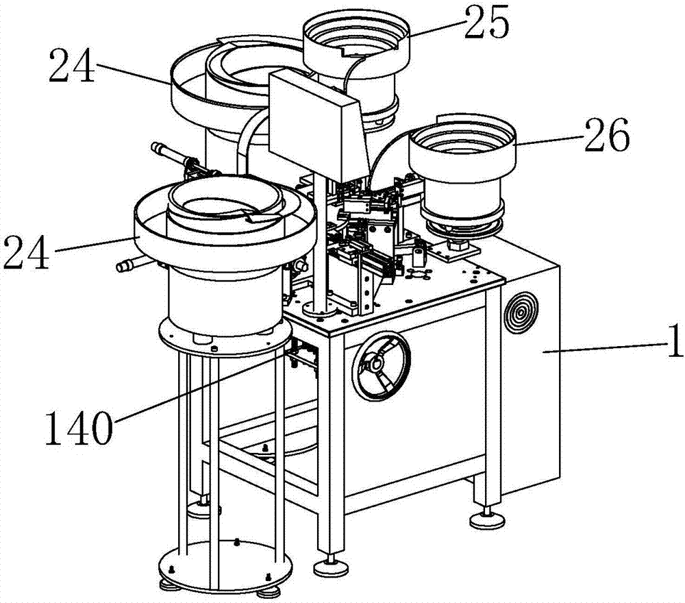
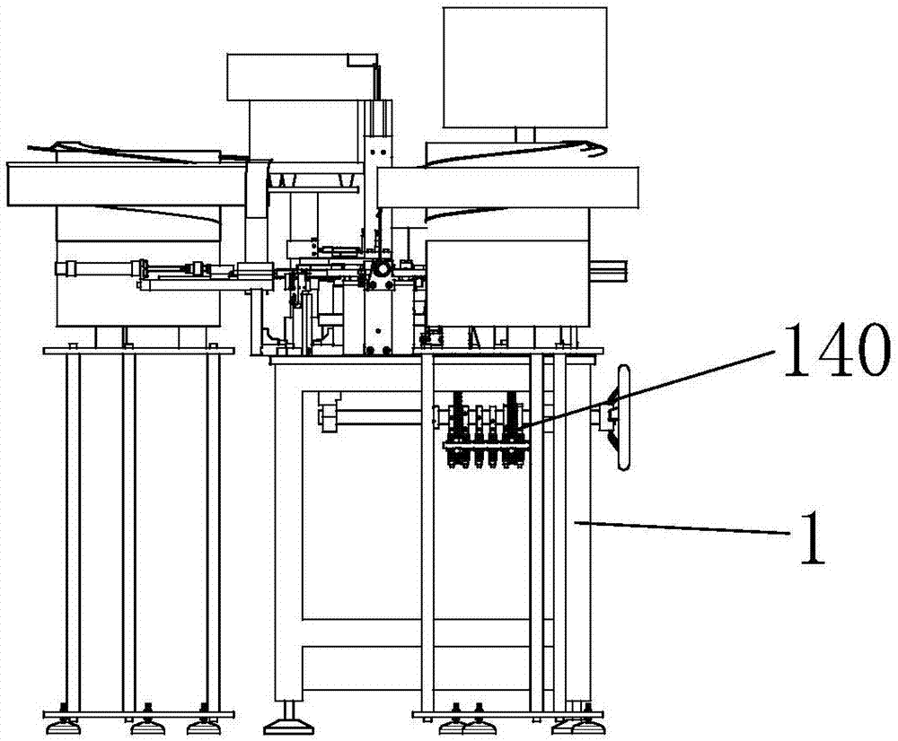
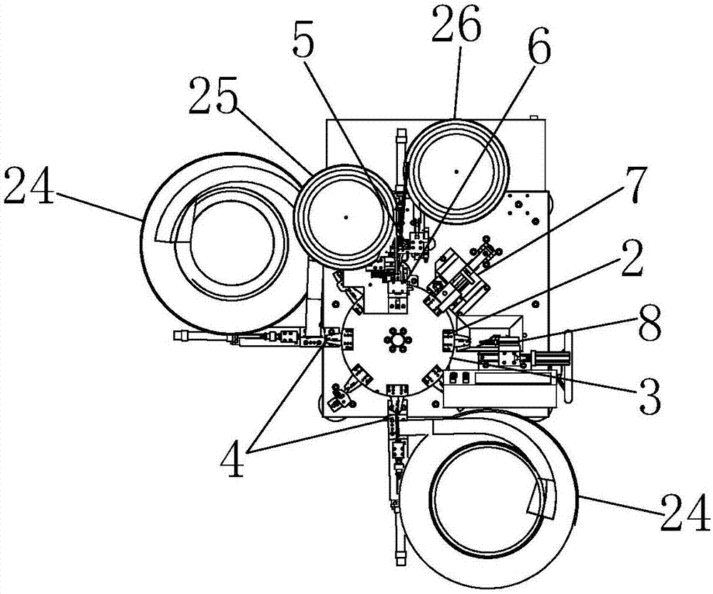
[0125] Such as Figure 1-13As shown, the clip automatic assembly machine includes a frame 1, and the frame 1 is provided with a rotating disk 3, a clip mounting mechanism 4, a spring mounting mechanism 5, a pin mounting mechanism 6, a pin pressing mechanism 7 and a material retrieving mechanism 8, and the rotating disk 3 is connected with the rotary driving device, the clamp seat 2 is installed on the rotating disk 3, the clip installation mechanism 4 is connected ...


PUM


Abstract

The invention belongs to the technical field of clamp assembly machines, and particularly relates to an automatic assembly machine of clamps. The automatic assembly machine comprises a rack, and a rotary disc, clamping piece mounting mechanisms, a spring mounting mechanism, a dowel mounting mechanism, a dowel pressing mechanism and a taking mechanism are arranged on the rack; the rotary disc is connected with a rotating driving device; clamping seats are mounted on the rotary disc; the clamping piece mounting mechanisms are connected with clamping piece input mechanisms; the spring mounting mechanism is connected with a spring input mechanism; the dowel pressing mechanism is connected with a dowel input mechanism; the dowel mounting mechanism comprises a dowel feeding seat and a dowel pushing rod; the dowel pushing rod is connected with a fourth driving device; and a first channel is formed in the dowel feeding seat. The automatic assembly machine is characterized in that a dowel clamping device is further arranged on the dowel feeding seat. The automatic assembly machine has the advantages that the dowel clamping device presses dowels, the dowels and the clamps on the clamping seats are accurately aligned, and accuracy of insertion of the dowels is improved.

Description

technical field [0001] The invention belongs to the technical field of clip assembly machines, in particular to an automatic clip assembly machine. Background technique [0002] The assembly of the clips is currently completed by the clip assembly machine. The first clip is sent into the clip seat through the first clip feeding mechanism, and then the clip seat is rotated to the next station, and the second clip is sent through the second clip feeding mechanism. The clip is sent into the clip seat, and then the clip seat is continuously rotated to the next station, the spring and the hinge shaft are sent between the first clip and the second clip, and finally the hinge shaft is riveted. [0003] Patent document [CN201620809549.X] discloses a hairpin articulated shaft assembly mechanism, including a feed seat, a push rod, a feed channel is provided on the feed seat, one end of the feed channel is the feed end, and the other One end is the discharge end, and the feed seat is ...

Claims


Application Information

Patent Timeline
IPC IPC(8): B23P21/00
CPCB23P21/006
Inventor 何道兵
Owner 浙江宏日自动化科技有限公司
Why Eureka
Try Eureka