
Rotary rolling die-cutting device

A rolling die and pressurizing device technology, applied in metal processing and other directions, can solve the problems of reduced strength, easily damaged die-cutting devices, cumbersome adjustments, etc., and achieve the effects of increasing service life, improving die-cutting accuracy, and flexible adjustment

Inactive Publication Date: 2018-05-04
JIANGSU QIHAO PRECISION MACHINERY
View PDF0 Cites 4 Cited by
  • Summary
  • Abstract
  • Description
  • Claims
  • Application Information

AI Technical Summary

Problems solved by technology

[0005] 1. Die-cutting ability and precision are relatively poor;
[0006] 2. The strength of the upper knife roller shaft and the lower knife roller shaft is reduced or broken due to the complex force, which shortens the service life of the upper knife roller and the lower knife roller;
[0007] 3. The manual screw pressurized structure is easy to deform the top plate and even the side plate, reducing the precision and service life of the die-cutting device;
[0008] 4. In the existing die-cutting device, the transmission device is a belt drive or a universal joint drive. When the belt drive or the coaxiality between the universal joint and the roller body is poor, the shaft end of the roller body is affected by radial force, so that the bearing The radial force is uneven, and the pressure device applies pressure to the slider, the radial force of the bearing is very large, and the bearing is easily damaged;
[0009] 5. In the existing die-cutting device, the upper slider and the lower slider slide up and down by friction. If the sliding gap is too small, it is easy to get stuck. When the sliding gap is too large, the sliding accuracy is low and other parts of the die-cutting device are easily damaged;
[0010] 6. The height of the lower knife roller cannot be adjusted freely
When the height of the material to be cut is adjusted, in order to adapt to the height of the material, it is often necessary to increase or decrease the height block, which is cumbersome to adjust, low in efficiency and high in cost

Method used


Image

  • Rotary rolling die-cutting device
  • Rotary rolling die-cutting device
  • Rotary rolling die-cutting device

Examples


Embodiment Construction

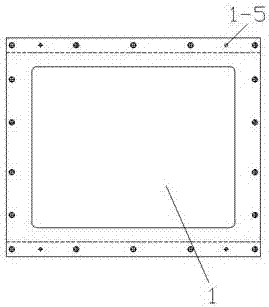
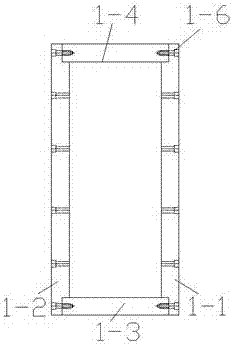
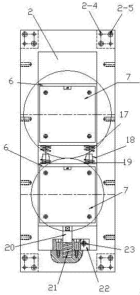
[0082] Such as figure 1 A rotary rolling die-cutting device shown, outer frame 1, inner frame 2, upper knife roller 3, lower knife roller 4, multiple sliding devices, pressure device, pressure relief device, position adjustment device, limit device , as well as the roller body cleaning device and the servo transmission device, the upper cutter roller 3 and the lower cutter roller 4 are arranged inside the inner frame, the sliding devices are respectively arranged at the two ends of the upper cutter roller 3 and the lower cutter roller 4, and the pressure relief device is arranged on Between the two sliding devices, the position adjustment device is set under the two ends of the lower knife roller, the servo transmission device is fixed on the outside of the inner frame, and the pressure device is fixed on the outer frame, wherein:

[0083] Outer frame 1 includes outer frame side plate a1-1, outer frame side plate b1-2, outer frame bottom plate 1-3, outer frame top plate 1-4, o...


PUM


Abstract

The invention discloses a rotary rolling die-cutting device. The rotary rolling die-cutting device is characterized by comprising an outer frame, an inner frame, an upper cutter roller, a lower cutterroller, multiple slide devices, a pressing device, a pressure unloading device, position adjusting devices, a limiting device, a roller body cleaning device and a servo transmission device; the uppercutter roller and the lower cutter roller are arranged in the inner frame; the slide devices are respectively arranged at the two ends of the upper cutter roller and the lower cutter roller; the pressure unloading device is arranged between two slide devices; the position adjusting devices are arranged below the two ends of the lower cutter rollers; the servo transmission device is fixed on the outer side of the inner frame; and the pressing device is fixed on the outer frame. Bearings in an upper bearing base and a lower bearing base are not influenced by pressing in work; the die-cutting effect can be effectively guaranteed; and in addition, the bearing bases can be prevented from sliding outside slide rails of linear bearings, or the cutter rollers are prevented from touching a distance determining rod on the inner frame. In later polishing of the upper cutter roller and the lower cutter roller, the inner frame only needs to be disassembled. The rotary rolling die-cutting device isnovel in structure, convenient to disassemble and high in efficiency.

Description

technical field [0001] The invention relates to the field of mechanical manufacturing, in particular to a rotary rolling die-cutting device. Background technique [0002] At present, with the rapid development of the economy, the application of rotary rolling die-cutting technology at home and abroad is becoming more and more extensive. The industry involves sanitary products, medical and sanitary products, beauty products, electronic products, leather products, various packaging, printing, trademarks label etc. [0003] The existing rotary rolling die-cutting device is a manual screw pressurized structure. When the rolling die-cutting device of this mechanism is working, the material to be cut is placed between the upper knife roller and the lower knife roller, and the pressure is applied downward by the pressure device. The upper slider drives the upper knife roller to slide down until it contacts the lower knife roller. When the pressure between the upper knife roller an...

Claims


Application Information

Patent Timeline
Patent Type & Authority Applications(China)
IPC IPC(8): B26F1/42B26D5/12B26D7/26B26D7/00
CPCB26F1/42B26D5/12B26D7/00B26D7/2628
Inventor 刘国孜乔利军刘艳旭
Owner JIANGSU QIHAO PRECISION MACHINERY
Learn More