Wood cutting device

A cutting device and wood technology, applied in sawing equipment, wood processing equipment, circular saws, etc., can solve the problems of difficult rotation of wood, achieve the effects of improving cutting quality and efficiency, simplifying processing, and improving work efficiency

Inactive Publication Date: 2018-05-04
邱超勇
View PDF6 Cites 9 Cited by
  • Summary
  • Abstract
  • Description
  • Claims
  • Application Information

AI Technical Summary

Problems solved by technology

[0004] Aiming at the deficiencies of the prior art, the present invention provides a wood cutting device, which solves the problem that the wood is not easy to rotate

Method used


Image

  • Wood cutting device
  • Wood cutting device
  • Wood cutting device

Examples


Embodiment Construction

[0021] The following will clearly and completely describe the technical solutions in the embodiments of the present invention with reference to the accompanying drawings in the embodiments of the present invention. Obviously, the described embodiments are only some, not all, embodiments of the present invention. Based on the embodiments of the present invention, all other embodiments obtained by persons of ordinary skill in the art without making creative efforts belong to the protection scope of the present invention.

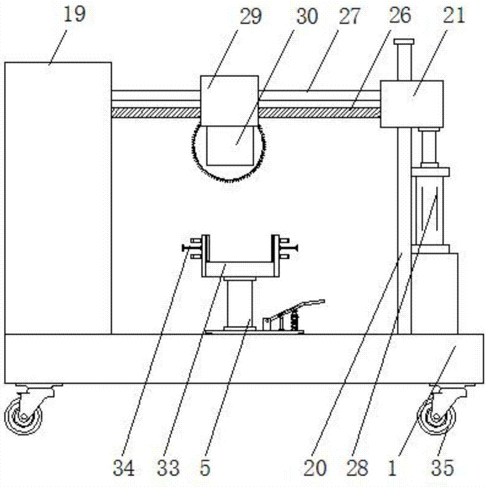
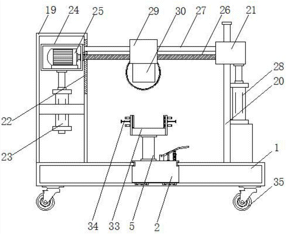
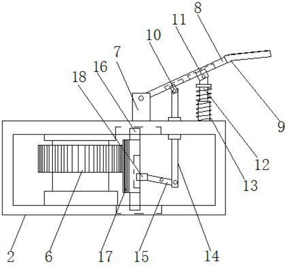
[0022] see Figure 1-4 , the present invention provides a technical solution: a wood cutting device, comprising a bottom box 1 and a rotary box 2, a moving groove 3 is provided inside the top plate of the bottom box 1, and a chute 4 is fixedly provided on both sides of the rotary box 2, The chute 4 is slidingly connected with the two sides of the moving groove 3, and the bottom of the inner cavity of the rotating box 2 is rotatably connected with a rotating sh...


PUM


Abstract

The invention discloses a wood cutting device and relates to the technical field of wood processing. The wood cutting device comprises a bottom box and a rotary box. A moving groove is formed in a topplate of the bottom box. Sliding grooves are fixedly formed in the upper portions of the two sides of the rotary box. The sliding grooves and the two sides of the moving groove are slidably connected. A rotary shaft is rotationally connected to the bottom of an inner cavity of the rotary box. The top end of the rotary shaft penetrates through the top plate of the rotary box and extends to the upper portion of the rotary box. A gear is fixedly installed on the surface of the rotary shaft and is located in the rotary box. A fixed block is fixedly installed at the top end of the rotary box. A first rotary rod is rotationally connected to the top end of the fixed block. A pedal is fixedly installed at the end, away from the fixed block, of the first rotary rod. The pedal drives the first rotary rod and a second rotary rod to rotate. The second rotary rod drives a gear block to be separated from the gear through a third sliding block and a moving rod. In this way, rotary adjustment can beconducted, workload of workers is reduced through the design, thus wood processing is simpler and more convenient, and work efficiency is improved.

Description

technical field [0001] The invention relates to the technical field of wood processing, in particular to a wood cutting device. Background technique [0002] In the process of mechanical processing, the common methods of plate cutting are manual cutting, semi-automatic cutting machine cutting and CNC cutting machine cutting. The working conditions are harsh and the production efficiency is low; among the semi-automatic cutting machines, the profiling cutting machine has better quality of cutting workpieces. Because it uses cutting molds, it is not suitable for cutting single pieces, small batches and large workpieces. Although other types of semi-automatic cutting machines are lower It reduces the labor intensity of workers, but its function is simple, and it is only suitable for cutting parts with regular shapes; compared with manual and semi-automatic cutting methods, CNC cutting can effectively improve the efficiency and quality of plate cutting, and reduce the labor inte...

Claims


Application Information

Patent Timeline
Patent Type & Authority Applications(China)
IPC IPC(8): B27B5/18B27B5/29
CPCB27B5/187B27B5/29
Inventor 邱超勇
Owner 邱超勇
Why Eureka
Try Eureka