Externally-clamping type full-automatic pipe cutting machine

A fully automatic, pipe cutting machine technology, applied in the direction of tubular objects, welding/cutting auxiliary equipment, auxiliary devices, etc., can solve the problems of inconvenient clamping, increased processing difficulty, and increased manufacturing costs.

Inactive Publication Date: 2017-08-18
东莞友联钣金科技有限公司
View PDF7 Cites 11 Cited by
  • Summary
  • Abstract
  • Description
  • Claims
  • Application Information

AI Technical Summary

Problems solved by technology

[0002] In the process of mechanical manufacturing, it is used to fix the processing object so that it occupies the correct position to accept the construction or inspection device. When the workpiece is processed on the machine tool, in order to make the surface of the workpiece reach the size, geometric shape and other surfaces specified in the drawing The mutual position accuracy and other technical requirements, the workpiece must be positioned, clamped and clamped before processing. The fixture is usually composed of a positioning element to determine the correct position of the workpiece in the fixture, and a clamping device. At present, the external card type in domestic factories Pipe cutting machines are all common traditional cutting equipment in the market. It is inconvenient to clamp. They can only be installed round and not square. They cannot achieve centering clamping and high-precision transmission of moving workpieces. It is difficult to process long and irregular workpieces. Most of the cutting methods are tool cutting with low precision and inflexibility, which leads to increased processing difficulty, greatly increases the workload of workers, and increases manufacturing costs.

Method used


Image

  • Externally-clamping type full-automatic pipe cutting machine
  • Externally-clamping type full-automatic pipe cutting machine
  • Externally-clamping type full-automatic pipe cutting machine

Examples


Embodiment Construction

[0022] In order to facilitate the understanding of those skilled in the art, the present invention will be further described below in conjunction with the examples, and the contents mentioned in the embodiments are not intended to limit the present invention.

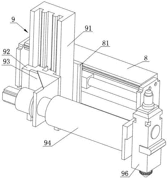
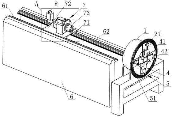
[0023] Such as Figure 1 to Figure 7 Shown is Embodiment 1 of the present invention, a kind of outer card type automatic pipe cutting machine, comprises frame 6, plasma cutting part 96, the elevating device 9 that is used to drive plasma cutting part 96 to move up and down, is fixed on frame 6 Double slide rails 61, the tailstock clamping device 7 that is movably installed on the double slide rails 61, and the feed drive mechanism 8 for driving the tailstock clamping device 7 to move back and forth, the front end of the frame 6 is fixedly provided with The fixed sleeve 1 is characterized in that: the fixed sleeve 1 is equipped with a rotatable drum 2, the frame 6 is equipped with a first drive mechanism 3 for driving th...


PUM


Abstract

The invention relates to the technical field of pipe cutting machines, in particular to an externally-clamping type full-automatic pipe cutting machine. A rotary rotating cylinder is arranged in a fixing sleeve. A rack is provided with a first drive mechanism used for driving the rotating cylinder to rotate. A rotating disc is fixed to the front end of the rotating cylinder. The rotating disc is provided with at least three clamping claw devices uniformly arranged in a ring shape. Each clamping claw device comprises an installing plate fixed to the rotating disc, a radial moving claw movably arranged on the installing plate, a lead screw connected with the radial moving claw, and a tensioning gear fixed to the outer end of the lead screw. The rotating cylinder is provided with a second drive mechanism used for driving the tensioning gears to rotate. Each radial moving claw is provided with a rolling sleeve. In the machining process, a workpiece can be moved front and back, and therefore the workpiece can follow rotation of the rotating cylinder and is fed and propelled conveniently, a plasma cutting part located on one side of the fixing sleeve is located to the place where cutting is needed through flexible moving of a supporting arm, and the externally-clamping type full-automatic pipe cutting machine can clamp and flexibly machine long-strip-shaped workpieces with triangular or rectangular sections, improves production efficiency and production quality and is very practical.

Description

technical field [0001] The invention relates to the technical field of pipe cutting machines, in particular to an outer card type automatic pipe cutting machine. Background technique [0002] In the process of mechanical manufacturing, it is used to fix the processing object so that it occupies the correct position to accept the construction or inspection device. When the workpiece is processed on the machine tool, in order to make the surface of the workpiece reach the size, geometric shape and other surfaces specified in the drawing The mutual position accuracy and other technical requirements, the workpiece must be positioned, clamped and clamped before processing. The fixture is usually composed of a positioning element to determine the correct position of the workpiece in the fixture, and a clamping device. At present, the external card type in domestic factories Pipe cutting machines are all common traditional cutting equipment in the market. It is inconvenient to clam...

Claims


Application Information

Patent Timeline
Patent Type & Authority Applications(China)
IPC IPC(8): B23K10/00B23K37/053
CPCB23K10/00B23K37/053B23K2101/06
Inventor 马墉良谭国荣
Owner 东莞友联钣金科技有限公司
Why Eureka
Try Eureka