Focal spot-and-focal depth-variable Bessel beam laser processing system and method

A Bessel beam and laser processing technology, which is applied in laser welding equipment, metal processing equipment, optics, etc., can solve the problem that the Bessel beam laser processing system cannot be applied to different hole types and material thicknesses, and achieve high quality and flexibility The effect of processing, meeting the processing needs, and adjusting the process is simple

Active Publication Date: 2020-08-07
XI'AN INST OF OPTICS & FINE MECHANICS - CHINESE ACAD OF SCI
View PDF11 Cites 10 Cited by
  • Summary
  • Abstract
  • Description
  • Claims
  • Application Information

AI Technical Summary

Problems solved by technology

[0005] In order to solve the problem that the existing Bessel beam laser processing system cannot be applied to the processing of different hole types and material thicknesses, the present invention proposes a Bessel beam processing system and method with variable focal spot focal depth. The Bessel beam processing system is adjusted to obtain a variable Bessel beam laser processing system with a focal spot and focal depth. Through this system, the focal depth of the Bessel beam focal spot can be processed to achieve large depth-to-diameter ratio micropores, transparent materials, etc. Multi-purpose processing provides guarantee for high-precision micro-hole pattern manufacturing and high-quality transparent material cutting, etc.

Method used


Image

  • Focal spot-and-focal depth-variable Bessel beam laser processing system and method
  • Focal spot-and-focal depth-variable Bessel beam laser processing system and method
  • Focal spot-and-focal depth-variable Bessel beam laser processing system and method

Examples


Embodiment Construction

[0038] The present invention will be described in detail below in conjunction with various embodiments shown in the drawings. However, these embodiments do not limit the present invention, and any structural, method, or functional changes made by those skilled in the art according to these embodiments are included in the protection scope of the present invention.

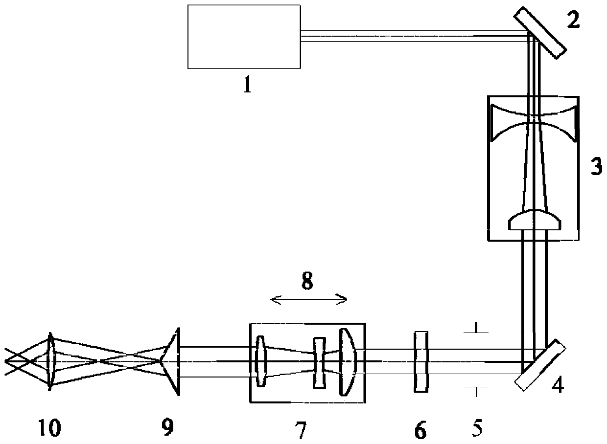
[0039] In order to solve the multi-purpose processing problem of an ultrafast laser device, the present invention designs a Bessel beam laser processing system with a variable focal spot focal depth. Such as figure 1 , the processing system includes a laser 1, a first mirror 2, a beam expander mirror 3, a second mirror 4, an aperture 5, a wave plate 6, a zoom lens 7, a high-precision translation stage 8, an axicon 9, and a lens 10 . The beam emitted from laser 1 is reflected by the first mirror placed at an angle of 45°, and after entering the beam expander for expansion and homogenization, it is reflected by the ...


PUM


Abstract

The invention belongs to the field of laser precision manufacturing and to a focal spot-and-focal depth-variable Bessel beam laser processing system and method and aims to solve the problem that an existing Bessel beam laser processing system cannot be suitable for processing different hole patterns and material thicknesses. The system comprises a laser, a beam expander, a diaphragm, a wave plate,a zoom lens, a positive axis pyramid and a lens, wherein the beam expander, the diaphragm, the wave plate, the zoom lens, the positive axis pyramid and the lens are sequentially arranged in the emergent light path of the laser; a light beam emitted from the laser is expanded and homogenized by the beam expander; the laser beam enters the diaphragm to be subjected to stray light filtering; after the filter laser beam reaches the wave plate and then enters the zoom lens, the focal length of the zoom lens and the distance between the zoom lens and the positive axis pyramid are adjusted, so thatthe focal spot and focal depth of the generated Bessel beam can be changed, and therefore, a required processing light beam is obtained; the light beam acts on the surface of a workpiece after being focused by the lens. By means of the system, the focal spot and focal depth changes of the processing Bessel beam can be realized, the multi-purpose processing of large-depth-diameter-ratio micropores,transparent materials and the like is achieved, and guarantees are provided for high-precision micropore pattern manufacturing, high-quality transparent material cutting and the like.

Description

technical field [0001] The invention belongs to the field of laser precision manufacturing, and relates to a processing system and method in which the processing beam is a Bessel beam and the focal depth of the focal spot of the beam is variable. Background technique [0002] At present, it is the most commonly used processing method in the field of laser micromachining to realize the processing of large depth-to-diameter ratio microholes and transparent materials through Bessel beams. Bessel processing beam generation is a key technology in the processing system, and its generation methods include axicons, annular slit lenses, spatial light modulators, and deformable mirrors. The axicon method has the advantages of low loss and low cost and has attracted widespread attention. [0003] In the processing of large depth-to-diameter ratio microholes and transparent materials, the requirements for processing beams are different according to the hole type and material thickness....

Claims


Application Information

Patent Timeline
Patent Type & Authority Applications(China)
IPC IPC(8): G02B27/09G02B27/28B23K26/06
CPCB23K26/0643B23K26/0648B23K26/0652G02B27/0911G02B27/0927G02B27/0955G02B27/0972G02B27/0977G02B27/286
Inventor 李明杨合宁
Owner XI'AN INST OF OPTICS & FINE MECHANICS - CHINESE ACAD OF SCI
Why Eureka
Try Eureka