
New type two dimension moving two dimension rotating parallel machine tool

A three-dimensional mobile and parallel technology, applied in metal processing, metal processing equipment, manufacturing tools, etc., to achieve good structural shock resistance and cutting stability, ensure processing accuracy, and reduce weight

Inactive Publication Date: 2004-03-03
SICHUAN UNIV
View PDF0 Cites 10 Cited by
  • Summary
  • Abstract
  • Description
  • Claims
  • Application Information

AI Technical Summary

Problems solved by technology

[0004] The parallel machine tool designed by the present invention takes advantage of the existing parallel mechanism and overcomes the deficiencies of the prior art, so that the parallel machine tool has the advantages of simple structure, flexible processing, high processing precision, fast processing speed, good processing technology, and controllability. Easy programming and other advantages can meet the user's requirements for multi-axis CNC machining of large-scale parts with complex surfaces

Method used


Image

  • New type two dimension moving two dimension rotating parallel machine tool
  • New type two dimension moving two dimension rotating parallel machine tool
  • New type two dimension moving two dimension rotating parallel machine tool

Examples


Embodiment 1

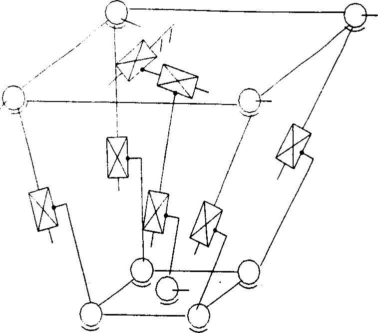
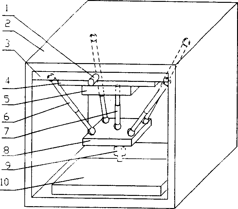
[0038] The principle of embodiment 1 is attached figure 1 As shown, the overall structure is as figure 2shown. The parallel machine tool of this embodiment consists of a frame 2, a fixed platform 3 fixed on the frame, a moving platform 8 on which a cutting tool 9 is installed, a workbench 10, and 5 connections connecting the fixed platform and the moving platform at both ends. legs pose. Five connecting legs form a space parallel closed chain structure with the moving platform and the fixed platform. Wherein the connecting leg 7 is located at the central position of the moving platform, and is designed with three moving pairs, one of which is an external moving pair 4, and the servo motor 1 is used as a driving device, and the components of the moving pair are connected with the fixed platform 3. Under the action of the external mobile pair 4, the connecting leg can perform telescopic movement. The other two moving pairs are built-in moving pairs, and this leg is connecte...

Embodiment 2

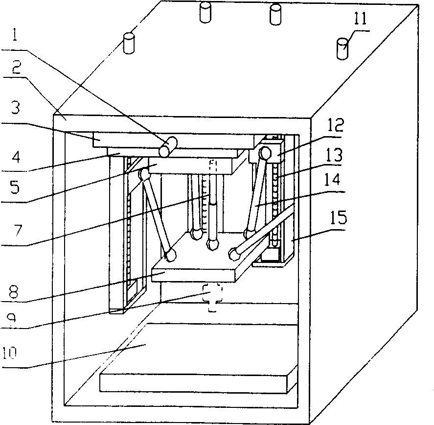
[0043] The overall structure of the parallel machine tool of the present embodiment is as attached image 3 As shown, its overall structure and the structure of a connecting leg 7 that contains three moving pairs are the same as in Embodiment 1, the difference is that four legs with the same structure of a moving pair are designed, and the structural legs are all formed by fixed length rods 14 and an outer mobile pair. The outer moving pair is composed of a guide rail 15 arranged on the frame 2, a ball screw 13, and a ball nut slider 12 configured with the guide rail and the ball screw. The slider 12 is driven by the servo motor 11 and the ball screw 13. Can slide up and down along the guide rail. One end of the fixed-length rod 14 is connected with the slider 12 through a Hooke hinge, and the other end is connected with the moving platform 8 through a spherical hinge. This embodiment also enables the cutting tool on the movable platform to obtain three-dimensional movement ...


PUM


Abstract

A 3D moving and 2D rotation parallel machine-tool is composed of fixed platform, moving platform for installing cutting tool, and bench. Said fixed and moving platforms are linked via 5 leg containing moving set. The central one of said legs contains 3 moving sets and Hooke pivot. One moving set is linked to the fixed platform. Other 4 legs are linked with fixed platform via Hooke pivots and with moving platform via ball-and-socket unit. Changing the extensions of 5 legs can realize 5-axle machining. Its advantages are high precision, stability and flexibility and low cost.

Description

1. Technical field [0001] The invention belongs to the technical field of numerical control machine tool manufacturing, and in particular relates to a novel parallel numerical control machine tool structural design. 2. Background technology [0002] Traditional CNC machine tools adopt a tandem mechanical structure. The disadvantages of this machine tool structure are bulky mechanism, many parts, long transmission chain, bulky, complex structure, expensive cost, uneven force and thermal deformation of various parts of the machine tool, and processing During the process, under the joint action of tension, pressure, bending moment and torque, the machine tool is prone to deformation and vibration, and the accumulation of errors leads to a decrease in machining accuracy. In addition, due to the heavy and bulky parts, the increase of speed and acceleration in the processing process is limited. [0003] In the existing parallel machine tool based on the 6-SPS parallel mechanism, ...

Claims


Application Information

Patent Timeline
Patent Type & Authority Applications(China)
IPC IPC(8): B23Q41/04
Inventor 徐礼钜李翔龙徐雪梅
Owner SICHUAN UNIV
Learn More