Power cable rack lifting device

A technology of lifting device and cable rack, applied in the direction of lifting device and lifting rack, etc., can solve the problems of unfavorable retracting and unwinding of cables, tipping of cable racks, inconvenient transportation, etc., and achieve the effects of easy manufacturing and promotion, convenient promotion and simple structure.

Inactive Publication Date: 2018-05-04
YANCHENG POWER SUPPLY CO STATE GRID JIANGSU ELECTRIC POWER CO +4
View PDF0 Cites 3 Cited by
  • Summary
  • Abstract
  • Description
  • Claims
  • Application Information

AI Technical Summary

Problems solved by technology

[0002] The power cable rack lifting device is a common appliance in electric power construction. Its main function is to install a large cable rack, which is convenient for the wheel to rotate and retract the cables. At present, the cable rack lifting device is usually equipped with wheels at the bottom to facilitate push-pull transportation. , but in the process of receiving and unwinding the line, the lifting device needs to be kept fixed on the ground and does not move. Then, due to the setting of the wheels, the lifting device is prone to offset and roll, and even it is prone to tipping when it bears a heavy cable rack, which affects the cable rack wheels. Reeling and unwinding the cable cannot meet both needs at the same time. The base of the existing lifting device is equipped with two wheels, which need to be tilted at a certain angle during transportation, which is inconvenient for transportation and consumes manpower. In addition, the shaft of the cable rack is prone to rolling on the lifting device. Not conducive to retracting cables

Method used


Image

  • Power cable rack lifting device
  • Power cable rack lifting device

Examples


Embodiment Construction

[0020] In order to deepen the understanding of the present invention, the present invention will be further described below in conjunction with the embodiments and accompanying drawings. The embodiments are only used to explain the present invention and do not constitute a limitation to the protection scope of the present invention.

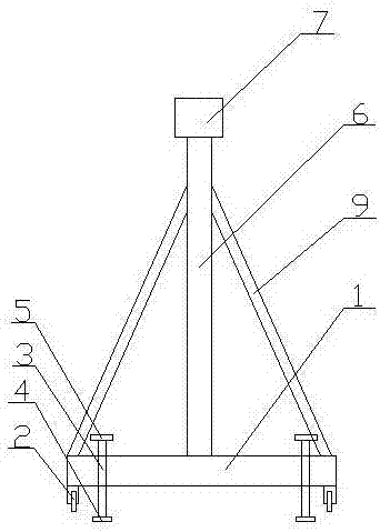
[0021] This embodiment is a lifting device for a power cable rack. The cable rack includes a wheel and a rotating shaft that runs through the wheel horizontally, such as figure 1 , figure 2 shown, including

[0022] A base mechanism, the base mechanism includes a rectangular base 1, wheels 2 placed on the front and rear sides below the base 1, a plurality of screw rods 3 are vertically penetrated through the base 1, and the plurality of screw rods 3 are placed on the front and rear sides of the base 1 Position and set close to the roller 2, the lower end of the screw 3 is provided with a support pad 4, and the upper end of the screw 3 is provid...


PUM


Abstract

The invention discloses a power cable rack lifting device. The power cable rack lifting device comprises a base mechanism, a support mechanism and a driving mechanism, wherein the base mechanism comprises a rectangular base, and wheels positioned on the front and back sides below the base; multiple screw rods vertically penetrate through the base, are positioned on the front and back sides of thebase, and are arranged near the wheels; support pad bodies are arranged at the lower ends of the screw rods; rotating handles are arranged at the upper ends of the screw rods; the support mechanism comprises two support rods correspondingly arranged in the horizontal direction and vertically arranged above the base; the two support rods are symmetrically arranged with the center of the base as axis; the upper ends of the two support rods are connected with a connecting rod transversely arranged; multiple through holes a are vertically formed in the support rods; and the through holes a on thetwo support rods are correspondingly arranged in sequence; the driving mechanism comprises a bearing body and a base body arranged up and down, and a cylinder positioned between the base body and thebearing body. The power cable rack lifting device has the advantages of simple structure, convenience to transport and prevention of rollover.

Description

Technical field: [0001] The invention relates to the field of electric power, in particular to a power cable rack lifting device. Background technique: [0002] The power cable rack lifting device is a common appliance in electric power construction. Its main function is to install a large cable rack, which is convenient for the wheel to rotate and retract the cables. At present, the cable rack lifting device is usually equipped with wheels at the bottom to facilitate push-pull transportation. , but in the process of receiving and unwinding the line, the lifting device needs to be kept fixed on the ground and does not move. Then, due to the setting of the wheels, the lifting device is prone to offset and roll, and even it is prone to tipping when it bears a heavy cable rack, which affects the cable rack wheels. Reeling and unwinding the cable cannot meet both needs at the same time. The base of the existing lifting device is equipped with two wheels, which need to be tilted ...

Claims


Application Information

Patent Timeline
Patent Type & Authority Applications(China)
IPC IPC(8): B66F7/16B66F7/28
CPCB66F7/16B66F7/28
Inventor 沈晓东陈万高程志南刘文庆
Owner YANCHENG POWER SUPPLY CO STATE GRID JIANGSU ELECTRIC POWER CO
Why Eureka
Try Eureka