Air cylinder structure based on magneto-rheological technology and controllable throwing robot based on magneto-rheological technology

A magnetorheological and robotic technology, applied in the field of robotics, can solve the problems of the distance and height of the thrown object being difficult to reach the expected value, the target being difficult to reach the destination point, the collision damage of the mechanical structure, etc.

Inactive Publication Date: 2018-05-04
CHONGQING UNIV
View PDF5 Cites 0 Cited by
  • Summary
  • Abstract
  • Description
  • Claims
  • Application Information

AI Technical Summary

Problems solved by technology

In this working mode of the cylinder, if the amount of work done by the cylinder cannot be accurately controlled, the distance and height of the thrown object will be difficult to reach the expected value, and the target will be difficult to reach the target point; It is easy to cause collision damage and energy loss to the mechanical structure

Method used


Image

  • Air cylinder structure based on magneto-rheological technology and controllable throwing robot based on magneto-rheological technology
  • Air cylinder structure based on magneto-rheological technology and controllable throwing robot based on magneto-rheological technology
  • Air cylinder structure based on magneto-rheological technology and controllable throwing robot based on magneto-rheological technology

Examples


Embodiment Construction

[0027] The present invention will be further described in detail below in conjunction with the drawings.

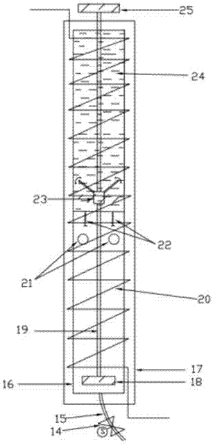
[0028] Such as figure 1 As shown, the present invention discloses a cylinder structure based on magnetorheological technology, which includes an inner sleeve 16, an internal piston 18, an external piston 25, a connecting rod 19 and a damping device 23, in which:

[0029] A partition in the inner sleeve 16 transversely arranged relative to the axial direction of the inner sleeve 16 separates the space inside the inner sleeve 16 into a first cavity and a second cavity, and the second cavity is arranged near the side wall of the partition There is a vent 21, a wire 20 connected to the power source is spirally wound on the outside of the inner sleeve 16, the inner sleeve 16 is made of a magnetically conductive material, and the end surface of the second cavity away from the partition is provided with an air source 6 connected to it. Source hole, the first cavity is filled with mag...


PUM


Abstract

The invention discloses an air cylinder structure based on the magneto-rheological technology. A partition plate which is transversely arranged in an inner sleeve relative to the axial direction of the inner sleeve divides the space inside the inner sleeve into a first cavity and a second cavity, the side wall of the portion, close to the partition plate, of the second cavity is provided with ventholes, a wire connected with a power source is spirally wound on the outer side of the inner sleeve, the end face, away from the partition plate, of the second cavity is provided with a gas source hole connected with a gas source, the first cavity is filled with magneto-rheological fluid, a connection rod is arranged in the axial direction of the inner sleeve and penetrates through the partitionplate, one end of the connection rod is connected with a piston arranged inside the second cavity, the other end of the connection rod stretches out of the end face, away from the partition plate, ofthe first cavity to be connected with a piston arranged outside, and a damping device is installed in the first cavity and fixedly connected with the connection rod. A stop block is added into an aircylinder, the improved technical scheme is carried out on the air cylinder structure based on the magneto-rheological technology, the air cylinder output pressure is controllable, the throwing hit rate of the robot is improved, and mechanical collision and energy loss are reduced.

Description

Technical field [0001] The invention relates to the technical field of robots, in particular to a cylinder structure and a controllable throwing robot based on magnetorheological technology. Background technique [0002] The China Robotics Competition is currently the highest and largest robot competition in China. The basketball robot project is an education and competition project that has emerged in recent years. The project provides a research on robot motion control, robot vision, and artificial intelligence. Standard test platform. As a common pneumatic actuator, the cylinder is inevitably involved in the robot system. It will be a very meaningful subject to study how to improve the design of the cylinder structure for a specific robot application field. [0003] The most basic structure of the cylinder is a built-in piston, an external piston, and a connecting rod connecting the inner and outer pistons. The working principle is to press the gas previously compressed in the ...

Claims


Application Information

Patent Timeline
Patent Type & Authority Applications(China)
IPC IPC(8): F15B15/14F15B15/22F15B21/06A63B69/40B25J11/00
CPCA63B69/0071A63B69/40B25J11/003F15B15/14F15B15/22F15B21/065
Inventor 王牛彭涛赵俊容王腾飞
Owner CHONGQING UNIV
Why Eureka
Try Eureka