Workpiece detecting, machining and positioning equipment

A technology for positioning equipment and workpiece detection, which is applied in the direction of workpiece clamping devices, measuring devices, manufacturing tools, etc., can solve the problems of unfavorable cost saving, high price of fixed roughness measuring instruments, etc., so as to broaden the scope of use, facilitate adjustment, easy-to-manufacture effects

Pending Publication Date: 2018-05-04
重庆朗奥机械有限公司
View PDF0 Cites 3 Cited by
  • Summary
  • Abstract
  • Description
  • Claims
  • Application Information

AI Technical Summary

Problems solved by technology

[0004] Aiming at the deficiencies in the prior art, the purpose of the present invention is to provide a workpiece detection, processing and positioning equipment, which solves the technical problem of the high price of the fixed roughness measuring instrument in the prior art, which is not conducive to cost saving

Method used


Image

  • Workpiece detecting, machining and positioning equipment
  • Workpiece detecting, machining and positioning equipment
  • Workpiece detecting, machining and positioning equipment

Examples


Embodiment

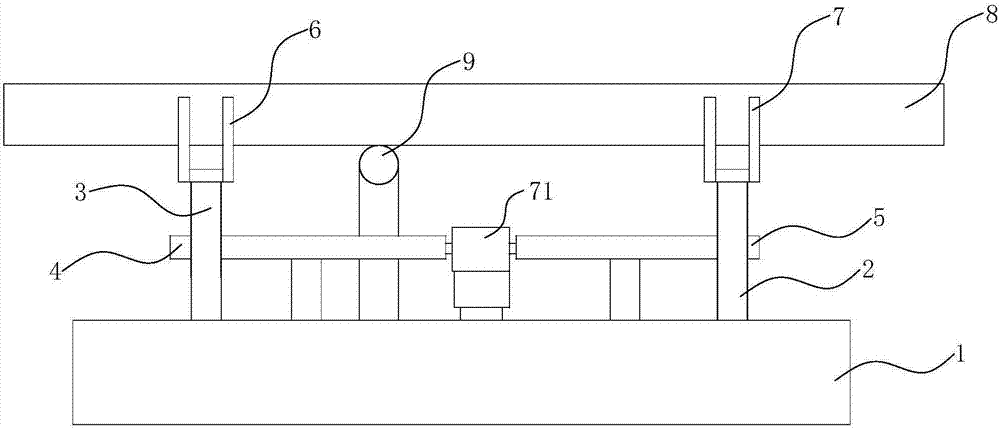
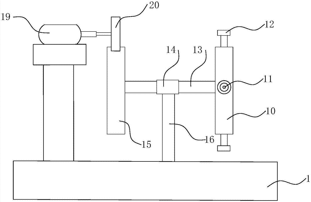
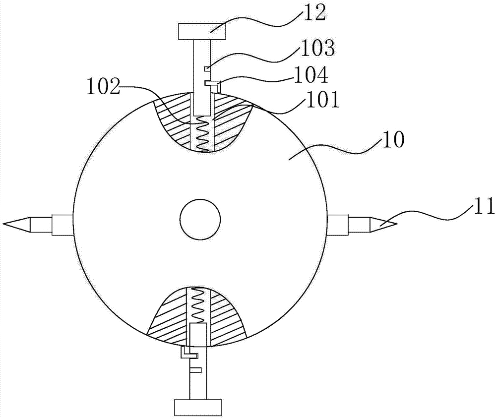
[0026] refer to Figure 1 to Figure 4 As shown: a workpiece detection, processing and positioning equipment, including a base 1 and a support mechanism and a detection mechanism 9 arranged on the base 1. The support mechanism is driven by a driving mechanism to adjust the support position of the workpiece 8; the support mechanism includes a left Support bar 3, right support bar 2 and the left support frame 6 that is arranged on the left support bar 3, the right support frame 7 that is arranged on the right support bar 2; Described driving mechanism comprises the first motor 71 and the left screw rod that is connected with it 4 and the right screw rod 5, the left support frame 6 and the right support frame 7 are driven by the left screw rod 4 and the right screw rod 5 to move toward / separate between the left support rod 3 and the right support rod 2; the workpiece 8 support mechanism Synchronized with the detection mechanism 9 on the same workbench, when processing the workpiec...


PUM


Abstract

The invention discloses workpiece detecting, machining and positioning equipment. A detection mechanism comprises a detection support plate, a plurality of detection probes and support structures arearranged on the periphery of the detection support plate at equal intervals, and the detection probes transmit detection data through sensors; each support structure comprises a T-shaped support seat,a spring and a limit assembly, a mounting hole is formed in the support plate, the T-shaped support seat is fixed in the mounting hole, and the spring is placed in the mounting hole and connected with the lower end of the T-shaped support seat; each limit assembly comprises a limit hole and a limit part, a limit hole is formed in a vertical rod of each T-shaped support seat, and each limit part is movably connected onto the detection support plate and matched with the corresponding limit hole for use; the detection support plate is driven by a drive mechanism to rotate, so that support of a workpiece by adjusting the T-shaped support seat or detection of the surface roughness of the workpiece by the detection probes can be realized.

Description

technical field [0001] The invention relates to the technical field of processing equipment, in particular to a workpiece detection, processing and positioning equipment. Background technique [0002] Surface roughness refers to the unevenness of small pitches and tiny peaks and valleys that a machined surface has. Surface roughness is described by the distance between two peaks or two troughs, the smaller the surface roughness, the smoother the surface. Surface roughness is closely related to the matching performance, wear resistance, fatigue strength, contact stiffness, vibration and noise of mechanical parts, and has an important impact on the service life and reliability of mechanical products. [0003] In order to detect the surface roughness of the workpiece, we need special roughness detection equipment. At present, there are generally separate hand-held roughness meters and a complete set of fixed roughness measuring instruments on the market. High, not conducive ...

Claims


Application Information

Patent Timeline
Patent Type & Authority Applications(China)
IPC IPC(8): G01B21/30B25B11/00
CPCG01B21/30B25B11/00
Inventor 陈东陈庆陈荣
Owner 重庆朗奥机械有限公司
Why Eureka
Try Eureka