Eureka AIR delivers breakthrough ideas for toughest innovation challenges, trusted by R&D personnel around the world.

Cooling device of transformer substation power transmission line

A cooling device and transmission line technology, applied in temperature control, non-electric variable control, instruments, etc., can solve the problems of increased energy consumption, inability to detect the temperature of transmission lines, long length of transmission lines, etc., to reduce use and energy consumption , increase the heat dissipation effect, the effect of low operating cost

Inactive Publication Date: 2018-05-04
宁波南顿电力科技有限公司
View PDF6 Cites 3 Cited by
  • Summary
  • Abstract
  • Description
  • Claims
  • Application Information

AI Technical Summary

Problems solved by technology

However, the existing technology has the following shortcomings: the temperature of the transmission line cannot be detected. When the temperature exceeds the heat limit value, the transmission line will be blown, and it will take a lot of time to re-install the transmission line. Secondly, the existing transmission line only relies on the outside world The natural wind dissipates heat, and the heat dissipation speed is very slow. When the temperature is high in summer, the transmission line cannot effectively cool down and dissipate heat, resulting in the burning of the transmission line
In this invention, the wire is installed in the water storage groove, and then the water is transported into the water storage groove by a circulating water pump, and the wire is in contact with the water to cool down the wire. The middle of the wire sags, and with the setting of water and water storage grooves, under their gravity, it is easier to make the wire sag, which increases the frequency of wire replacement. Secondly, the automatic water adding mechanism of the invention uses the water in the well , the submersible pump is used to transport water to the water storage groove to cool the wire, the length of the transmission line is longer, the water is more, and the energy consumption is increased. At the same time, the wire is set in the water storage groove, and the lower part of the wire is in the storage The inside of the water groove is also not conducive to the heat dissipation of the wire

Method used


Image

  • Cooling device of transformer substation power transmission line

Examples


Embodiment Construction

[0019] Further detailed explanation through specific implementation mode below:

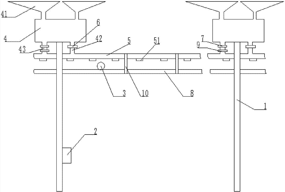
[0020] The reference signs in the drawings of the description include: electric pole 1, microcontroller 2, temperature sensor 3, insulated water storage tank 4, rainwater receiving tank 41, water inlet conduit 42, water outlet conduit 43, water pipe 5, sprinkler head 51, solenoid valve 6. One-way valve 7, wire 8, water pump 9, wire clamp 10.

[0021] Such as figure 1 Shown is a schematic diagram of the structure of the power line cooling device of the substation, including a power supply and a microcontroller 2, wherein the power supply is a solar power generation device, which is pollution-free and has low operating costs. An insulating water storage tank 4 is fixedly installed on the top of the pole 1, and two rainwater receiving tanks 41 are fixedly installed above the insulating water storage tank 4, and the rainwater receiving tank 41 is a funnel shape, which increases the area for receivin...


PUM


Abstract

The invention relates to the technical field of transformer substation power transmission lines, in particular to a cooling device of a transformer substation power transmission line. The cooling device comprises a power source, a miniature controller, a wire detection mechanism, a water storage mechanism and a cooling mechanism, the wire detection mechanism comprises a temperature sensor arrangedon a wire and connected with the miniature controller, the water storage mechanism comprises an insulating water storage box erected at the upper end of a pole, a rainwater collecting tank is fixedlyinstalled at the upper end of the insulating water storage box, a water inlet conduit and a water outlet conduit are fixedly installed at the lower end of the insulating water storage box, a solenoidvalve connected with the miniature controller is fixedly installed on the water inlet conduit, the cooling mechanism comprises a water pipe arranged at the upper portion of the wire, several nozzlesare fixedly installed below the water pipe, the water inlet conduit is fixedly connected to one end of the water pipe, and the water outlet conduit is connected to the other end of the water pipe. Thetemperature of the transformer substation power transmission line can be measured, and when the temperature is raised, the wire is cooled.

Description

technical field [0001] The invention relates to the technical field of substation transmission lines, in particular to a cooling device for substation transmission lines. Background technique [0002] With the deepening of the reform of the power system, power companies have entered into market-oriented applications, and higher requirements have been put forward for the reliability of power supply in terms of economic benefits and high-quality services. With the continuous rapid growth of urban and rural economies, the demand for electricity consumption in production and living is increasing day by day, and the electricity consumption is increasing rapidly. improve. [0003] At present, when the domestic power system is designing and erecting transmission lines, the transmission lines are often burned due to temperature rise, so measuring the temperature rise of the wires has become an important task to ensure that the existing transmission lines will not fail due to temper...

Claims


Application Information

Patent Timeline
Patent Type & Authority Applications(China)
IPC IPC(8): G05D23/20
CPCG05D23/20
Inventor 邱红光
Owner 宁波南顿电力科技有限公司
Why Eureka
Eureka Blog
Learn More