Coating device for outer bottom surface of steel immersed tube of bridge and tunnel

A coating equipment and immersed tube technology, applied in the direction of spraying device, etc., can solve the problems of difficulty in ensuring the coating quality of bridge and tunnel steel structures, the inability to complete the automatic spraying method of small workpieces, and the uncontrollable influence of spraying quality. Achieve the effect of facilitating large-span operations, ensuring stability and improving safety

Pending Publication Date: 2018-05-08
JIANGSU CUMT DAZHENG SURFACE ENG TECH
View PDF5 Cites 0 Cited by
  • Summary
  • Abstract
  • Description
  • Claims
  • Application Information

AI Technical Summary

Problems solved by technology

Among them, the preparatory work such as full mixing of materials and precise proportioning is highly dependent on personnel; secondly, although the more commonly used small air and airless spraying equipment are strong in mobility, they are difficult to achieve in terms of paint proportioning, instant mixing and spraying, and spraying width. Insufficient performance in terms of control and long-term stable operation, and the quality of spraying is greatly affected by the uncontrollability of the technical level of personnel, it is difficult to guarantee the quality of large-scale painting of bridge and tunnel steel structures
[0003] It is the first large-scale application of steel immersed tubes in the subsea tunnel of the deep and middle channel, which is the first case in the world. Its standard pipe section is 46 meters wide and 10.6 meters high, which is also among the top in the world. The protective coating construction of the outer bottom surface is particularly important, and the weight of each small segment of steel immersed tube is 300-400t, and the automatic spraying method of small workpieces running by themselves cannot be completed

Method used


Image

  • Coating device for outer bottom surface of steel immersed tube of bridge and tunnel
  • Coating device for outer bottom surface of steel immersed tube of bridge and tunnel
  • Coating device for outer bottom surface of steel immersed tube of bridge and tunnel

Examples


Embodiment Construction

[0033] In order to make the object, technical solution and advantages of the present invention clearer, the present invention will be further described in detail below with reference to the accompanying drawings and embodiments. However, it should be understood that the specific embodiments described here are only used to explain the present invention, and are not intended to limit the scope of the present invention.

[0034] Unless otherwise defined, all technical terms and scientific terms used herein have the same meaning as commonly understood by those skilled in the technical field of the present invention, and the terms used in the description of the present invention herein are only to describe specific implementations The purpose of the example is not intended to limit the present invention.

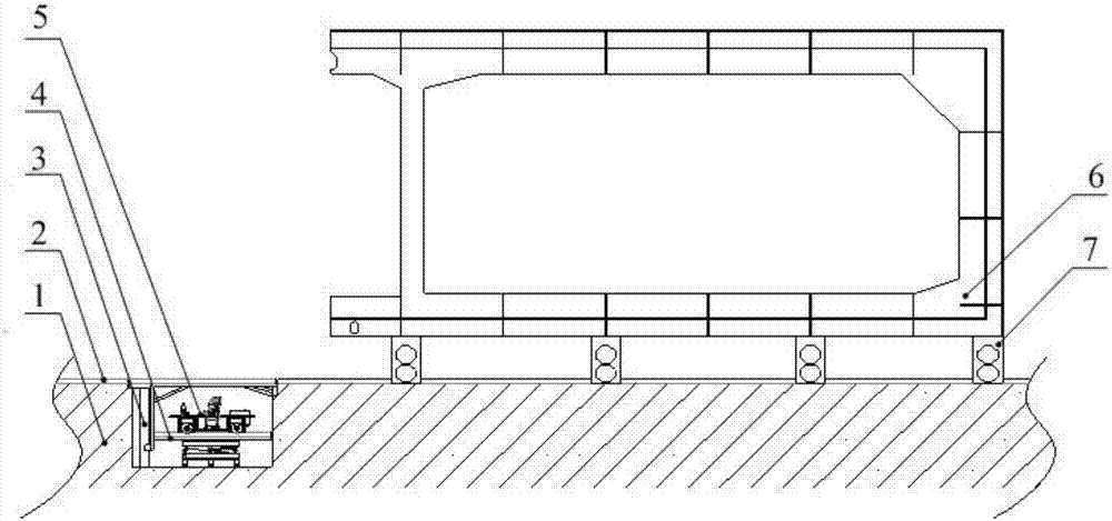
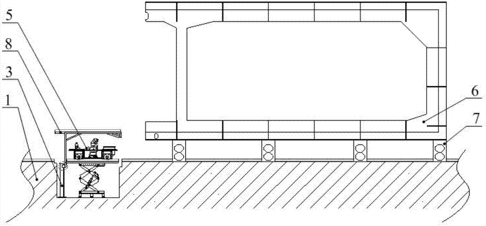
[0035] Such as figure 1 , figure 2 with Figure 8 As shown, a kind of outer bottom surface coating equipment of bridge and tunnel steel immersed pipes, including a spraying t...


PUM


Abstract

The invention discloses a coating device for an outer bottom surface of a steel immersed tube of a bridge and a tunnel, and belongs to the technical field of bridge and tunnel construction. The coating device comprises a spraying coating trolley for coating a small section of the steel immersed tube, a hidden lifting platform for positioning the spraying coating trolley, and a supporting platformwhich is positioned at the bottom part of the hidden lifting platform, wherein the hidden lifting platform is mounted in a concrete ground; a U-shaped gap is formed in the concrete ground, and the hidden lifting platform is positioned in the U-shaped gap; a track is arranged on the surface of the concrete ground; the hidden lifting platform comprises a hidden platform steel framework; other tracksare arranged at the upper end and the lower end of the hidden lifting platform steel framework; the spraying coating trolley is positioned on the track at the lower end of the hidden lifting platformframework and can move along the track; the supporting platform is fixed to the concrete ground and capable of driving the spraying coating trolley in the hidden lifting platform to lift up and down.With the adoption of the device, the coating quality can be effectively ensured, and the construction efficiency is improved.

Description

technical field [0001] The invention relates to a coating device for the outer bottom surface of steel immersed pipes of bridges and tunnels, and belongs to the technical field of bridges and tunnels construction. Background technique [0002] The construction of bridges and tunnels is an important project in the strategic planning of complex transportation networks, which is related to the national plan. Steel structure engineering has the characteristics of fast construction speed and strong load-bearing capacity, and is widely used. Taking the coating construction of large-scale bridge and tunnel steel structures as an example, there are many defects. Human-based painting methods are more common in bridge and tunnel steel structure painting workshops. Among them, the preparatory work such as full mixing of materials and precise proportioning is highly dependent on personnel; secondly, although the more commonly used small air and airless spraying equipment are strong in...

Claims


Application Information

Patent Timeline
Patent Type & Authority Applications(China)
IPC IPC(8): B05B13/02B05B13/04
CPCB05B13/0221B05B13/0431
Inventor 左新龙倪雅李紫跃刘国彬周春侠赵青青王金明周忠振孟凡浩高昊邵宁闵亮徐迪张安永陈天健刘贞冷阳光许丽丽
Owner JIANGSU CUMT DAZHENG SURFACE ENG TECH
Why Eureka
Try Eureka