
Cutting device used for globar machining

A technology of cutting device and silicon carbon rod, which is applied in the direction of fine working device, stone processing equipment, working accessories, etc., to achieve the effect of simple structure, improved cutting effect and convenient operation

Inactive Publication Date: 2018-05-08
河南科睿机械工程研究服务有限公司
View PDF0 Cites 3 Cited by
  • Summary
  • Abstract
  • Description
  • Claims
  • Application Information

AI Technical Summary

Problems solved by technology

[0003] The purpose of the present invention is to solve the problem of precise cutting of silicon carbon rods in the prior art, and propose a cutting device for processing silicon carbon rods

Method used


Image

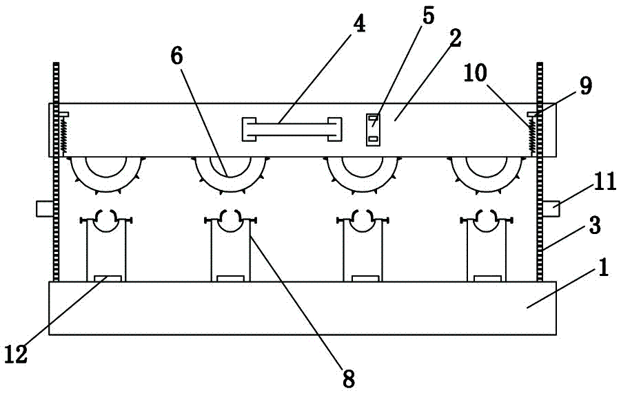
  • Cutting device used for globar machining
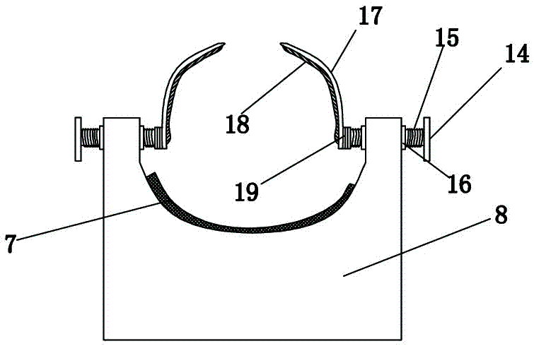
  • Cutting device used for globar machining
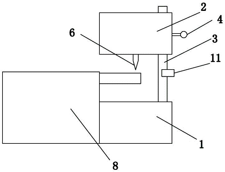
  • Cutting device used for globar machining

Examples


Embodiment Construction

[0017] The following will clearly and completely describe the technical solutions in the embodiments of the present invention with reference to the accompanying drawings in the embodiments of the present invention. Obviously, the described embodiments are only some, not all, embodiments of the present invention.

[0018] In describing the present invention, it should be understood that the terms "upper", "lower", "front", "rear", "left", "right", "top", "bottom", "inner", " The orientation or positional relationship indicated by "outside", etc. is based on the orientation or positional relationship shown in the drawings, and is only for the convenience of describing the present invention and simplifying the description, rather than indicating or implying that the referred device or element must have a specific orientation, so as to Specific orientation configurations and operations, therefore, are not to be construed as limitations on the invention.

[0019] refer to Figure ...


PUM


Abstract

The invention discloses a cutting device used for globar machining. The cutting device used for the globar machining comprises a base; bar fixing tables are fixedly arranged at the back side of the base; sliding rods are arranged at both sides of the top end of the base and the sliding rods penetrate through the interior of a shell hood; tape grooves are formed in the top end of the base and cutting plates are arranged at the bottom end of the shell hood; a handle and a controlling panel are arranged at the surface of the shell hood and the handle is located at the left side of the controllingpanel; bolt grooves are arranged at one side of each bar fixing table and a bolt rod is arranged in the corresponding bolt groove; a rotary handle is fixed at the right side of each bolt rod and a rotary shaft is arranged at the left side of the corresponding bolt rod; the bolt rods are connected with fixing plates by the rotary shafts. According to the device, the distances of the parts with theneed for cutting of bar bodies can be accurately measured by tapes in the tape grooves before the bar bodies are cut, and then the bar bodies are cut, so that a more accurate cutting effect can be achieved and the practicality can be better.

Description

technical field [0001] The invention relates to the technical field of cutting, in particular to a cutting device for processing silicon carbon rods. Background technique [0002] Silicon carbide rods are rod-shaped and tubular non-metallic high-temperature electric heating elements made of high-purity green hexagonal silicon carbide as the main raw material, processed into blanks according to a certain material ratio, and sintered at 2200°C for high-temperature siliconization, recrystallization and sintering. The normal use temperature in an oxidizing atmosphere can reach 1450°C, and the continuous use can reach 2000 hours. In the installation of silicon carbide rods, it needs to be cut precisely. The existing cutting equipment does not have good precision cutting performance, resulting in The silicon carbide rod after cutting cannot be used normally, which delays the work efficiency and production cost. In order to solve this kind of problem, a good cutting device is neede...

Claims


Application Information

Patent Timeline
IPC IPC(8): B28D5/04B28D7/04B28D7/00
CPCB28D5/04B28D5/0058B28D5/0082
Inventor 程丝雨周剑峰
Owner 河南科睿机械工程研究服务有限公司
Learn More