
High and low united bicycle tire pressure system

A bicycle and tire pressure technology, which is applied to vehicle parts, tire parts, and independent inflatable cushions, etc., can solve the problems of increasing the rider's force load, flat tires, and complicated design, so as to improve portability, Reduce tire pressure and improve traction

Inactive Publication Date: 2018-05-08
潘兆坤
View PDF3 Cites 0 Cited by
  • Summary
  • Abstract
  • Description
  • Claims
  • Application Information

AI Technical Summary

Problems solved by technology

[0002] Bicycles are divided into mountaineering off-road vehicles, technical bicycles and road racing vehicles according to different uses. The biggest difference between the various types of vehicles lies in the different tire structures used. Taking mountaineering off-road vehicles as an example, the tire functions focus on having good performance. Therefore, the tire pattern is full of tread and the design is complicated; taking the road racing car as an example, in order to seek speed, the design of the tread pattern is deliberately omitted in the central part of the tread, because the tread pattern structure will increase the rolling resistance and increase Rider's force load, it is not easy to prepare tires for mountain bikes, because if they are too hard, the traction will be reduced, and if they are too soft, the tires will be flattened. Therefore, a The high and low integrated bicycle tire pressure system that solves the above problems is really necessary

Method used


Image

  • High and low united bicycle tire pressure system
  • High and low united bicycle tire pressure system
  • High and low united bicycle tire pressure system

Examples


Embodiment Construction

[0020] The accompanying drawings are for illustrative purposes only, and should not be construed as limitations on this patent; in order to better illustrate this embodiment, certain components in the accompanying drawings will be omitted, enlarged or reduced, and do not represent the size of the actual product; for those skilled in the art It is understandable that some well-known structures and descriptions thereof may be omitted in the drawings.

[0021] In the description of the present invention, it should be noted that unless otherwise specified and limited, the terms "installation" and "connection" should be understood in a broad sense, for example, it can be a fixed connection, a detachable connection, or an integral Ground connection; it can be a mechanical connection or an electrical connection; it can be a direct connection or an indirect connection through an intermediary. It can be said that the internal communication of two components. Those of ordinary skill in ...


PUM


Abstract

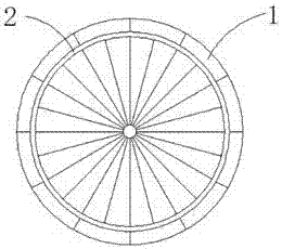
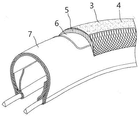
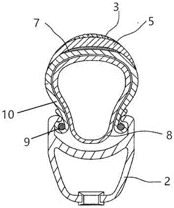
The invention relates to the field of tires, in particular to a high and low united bicycle tire pressure system. The high and low united bicycle tire pressure system comprises a wheel frame and an air faucet valve fixed to the wheel frame and further comprises a high and low air pressure system. The high and low air pressure system comprises a bottom layer air tire chamber, a middle layer inner tire chamber and an outer layer tire cover chamber. The bottom layer air tire chamber is attached to the inner side of the edge of the wheel frame, one end of the middle layer inner tire chamber abutsagainst the bottom layer air tire chamber, and the other end of the middle layer inner tire chamber makes contact with the outer layer tire cover chamber. The outer layer tire cover chamber is embedded into the edge of the wheel frame, and the bottom layer air tire chamber and the middle layer inner tire chamber are coated with the outer layer tire cover chamber. A low-pressure vacuum gap is reserved between the middle layer inner tire chamber and the outer layer tire cover chamber. According to the high and low united bicycle tire pressure system, the air pressure can reach to the maximum, ahigh-pressure tire is used to prevent flatness, a guide pipe is arranged in the high and low united bicycle tire pressure system, thus a low-pressure space is reserved in the high and low united bicycle tire pressure system, and meanwhile, good traction force is provided.

Description

technical field [0001] The invention relates to the field of tires, in particular to a high-low integrated bicycle tire pressure system. Background technique [0002] Bicycles are divided into mountaineering off-road vehicles, technical bicycles and road racing vehicles according to different uses. The biggest difference between the various types of vehicles lies in the different tire structures used. Taking mountaineering off-road vehicles as an example, the tire functions focus on having good performance. Therefore, the tire pattern is full of tread and the design is complicated; taking the road racing car as an example, in order to seek speed, the design of the tread pattern is deliberately omitted in the central part of the tread, because the tread pattern structure will increase the rolling resistance and increase Rider's force load, it is not easy to prepare tires for mountain bikes, because if they are too hard, the traction will be reduced, and if they are too soft, ...

Claims


Application Information

Patent Timeline
Patent Type & Authority Applications(China)
IPC IPC(8): B60C5/02B60C19/12
CPCB60C5/02B60C19/12
Inventor 潘兆坤
Owner 潘兆坤
Learn More