
Robotic fish used for tail fin impetus research

A technology of driving force and robotic fish, applied in the direction of mechanical gear transmission, non-rotating propulsion components, etc., can solve the problems of complex design and processing, reduce the efficiency of the research process, delay the research process, etc., achieve low cost, easy disassembly, The effect of stable transmission torque

Inactive Publication Date: 2018-05-08
ZHENGZHOU LONGWEI ELECTRONICS TECH CO LTD
View PDF0 Cites 0 Cited by
  • Summary
  • Abstract
  • Description
  • Claims
  • Application Information

AI Technical Summary

Problems solved by technology

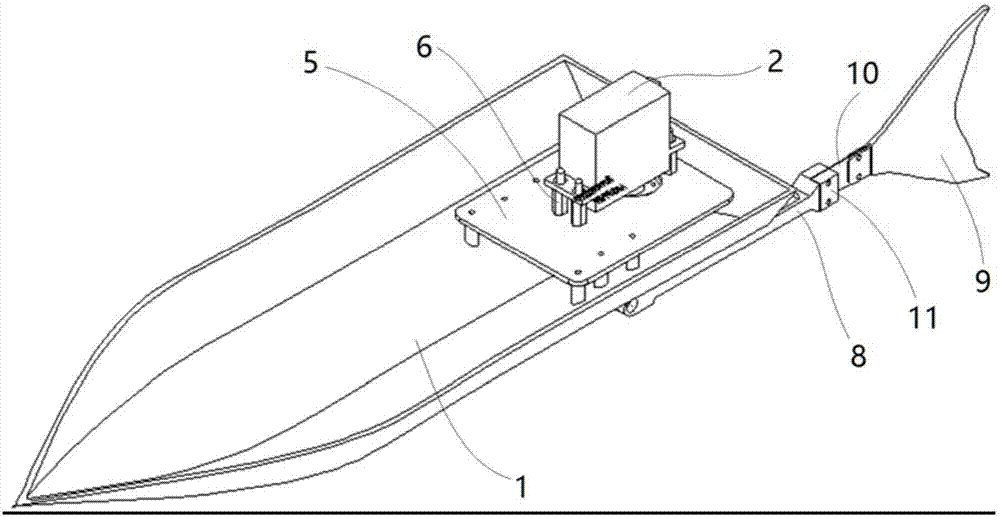
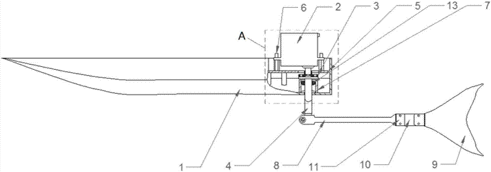
[0002] At present, in order to realize the tail fin propulsion research of the fish tail, it is generally necessary to make a tail fin propelled bionic robot fish. The existing technology generally makes a shell that is basically the same shape as the fish, and then sets a complex transmission mechanism inside the fish-shaped shell. Therefore, the caudal fin of the robotic fish is driven from the inside, and it is necessary to ensure that the robotic fish is at a certain depth in the water. For this reason, a series of structures or devices that can ensure that the robotic fish is at a certain depth must be installed, which makes the design and processing of the robotic fish extremely complicated. When it is necessary to frequently adjust the size, driving force, etc. in order to obtain multiple sets of parameters for experimental research, the complexity of this robotic fish greatly reduces the efficiency of the research process and delays the research process

Method used


Image

  • Robotic fish used for tail fin impetus research
  • Robotic fish used for tail fin impetus research
  • Robotic fish used for tail fin impetus research

Examples


Embodiment Construction

[0021] The following will clearly and completely describe the technical solutions in the embodiments of the present invention with reference to the accompanying drawings in the embodiments of the present invention. Obviously, the described embodiments are only some, not all, embodiments of the present invention. Based on the embodiments of the present invention, all other embodiments obtained by persons of ordinary skill in the art without making creative efforts belong to the protection scope of the present invention.

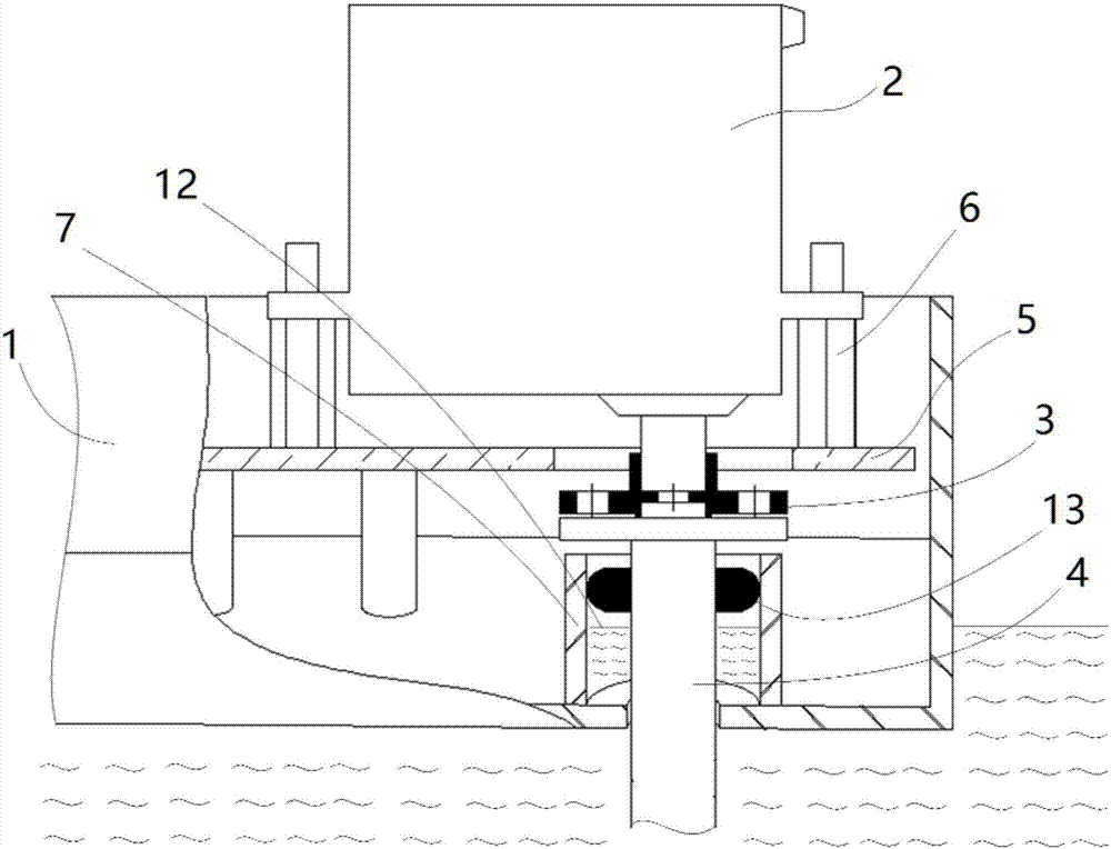
[0022] Such as figure 1 and figure 2 As shown, the robotic fish for tail fin propulsion research includes a hull 1, and the structure of the hull 1 is the prior art, so it will not be repeated. The bottom of the rear end of the hull 1 is provided with a perforation, and a support plate 5 is fixed above the perforation, and a steering gear 2 is fixed on the support plate 5 by a copper column 6 and a nut. The output shaft of the steering gear 2 is arranged dow...


PUM


Abstract

The invention discloses a robotic fish used for tail fin impetus research. A tail board, an elastic sheet and a tail handle are equivalent to a fishtail, a hull floats on the water surface, and the tail board, the elastic sheet and the tail handle extend underwater through a transmission column. The simple self-waterproof robotic fish is provided, the tail board, the elastic sheet and the tail handle are equivalent to the fishtail, the hull floats on the water surface, the tail board, the elastic sheet and the tail handle extend underwater through the transmission column, the front end of thetail handle is connected with a rectangular prism structure at the lower end of the transmission column through a clamping part, the effects that detachment is convenient and the driving torque is stable are achieved, the rear end of the tail handle is connected with the tail board through the elastic sheet, the elastic sheet is arranged to imitate flexible swings of the fishtail, and the swing frequency and the swing range of the tail handle are adjusted through a steering engine. The requirement for tail fin impetus research is met through the structure, the structure is simple, detachment and installation are convenient, cost is low, and a variable can be changed conveniently.

Description

technical field [0001] The invention relates to a robotic fish used for the research of caudal fin propulsion. Background technique [0002] At present, in order to realize the tail fin propulsion research of the fish tail, it is generally necessary to make a tail fin propelled bionic robot fish. The existing technology generally makes a shell that is basically the same shape as the fish, and then sets a complex transmission mechanism inside the fish-shaped shell. Therefore, the caudal fin of the robotic fish is driven from the inside, and it is necessary to ensure that the robotic fish is at a certain depth in the water. For this reason, a series of structures or devices that can ensure that the robotic fish is at a certain depth must be installed, which makes the design and processing of the robotic fish extremely complicated. When it is necessary to frequently adjust the size, driving force, etc. in order to obtain multiple sets of parameters for experimental research, th...

Claims


Application Information

Patent Timeline
Patent Type & Authority Applications(China)
IPC IPC(8): B63H1/36B63H23/04
CPCB63H1/36B63H23/04
Inventor 王波
Owner ZHENGZHOU LONGWEI ELECTRONICS TECH CO LTD
Learn More