
Supporting device used for building

A support device and construction technology, which is applied in the processing of building materials, construction, and on-site preparation of building components, etc., can solve the problems affecting the life safety of construction workers, the inability to adjust the height of the cushion in time, and the easy bending of a single support rod. , to achieve the effect of increasing practicability, reducing work efficiency and increasing support effect

Inactive Publication Date: 2018-05-08
余健亭
View PDF4 Cites 2 Cited by
  • Summary
  • Abstract
  • Description
  • Claims
  • Application Information

AI Technical Summary

Problems solved by technology

[0002] In many places in the construction industry, it is necessary to raise the support to facilitate construction. For example, when laying bricks on the wall, the bottom brick is often a certain distance from the ground. The level is neat, this method is not only inefficient, but also the height of the cushion cannot be adjusted in time
In addition, due to the unevenness of the cushion, the construction effect of tiling is poor, and it is easy to rework
At present, there is no special tool on the market that can solve this problem. In addition, if the support is not on a horizontal plane, it is difficult to find a suitable support block to support it. In construction auxiliary equipment, as one of the supporters , can support the required support according to the construction personnel, while the existing building supports are mostly supported by a single support rod, the overall structure is single, and the supporting force is limited
The supporting force on the building is basically large, so the single support rod is easy to bend when used, which seriously affects the life safety of construction personnel

Method used


Image

  • Supporting device used for building
  • Supporting device used for building

Examples


Embodiment Construction

[0023] The following will clearly and completely describe the technical solutions in the embodiments of the present invention with reference to the accompanying drawings in the embodiments of the present invention. Obviously, the described embodiments are only some, not all, embodiments of the present invention. Based on the embodiments of the present invention, all other embodiments obtained by persons of ordinary skill in the art without making creative efforts belong to the protection scope of the present invention.

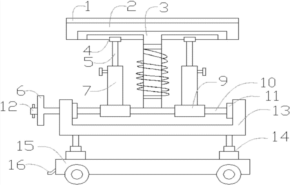
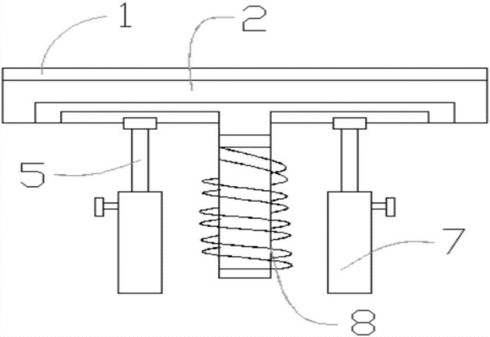
[0024] see Figure 1-2 , the present invention provides a technical solution: a support device for construction, including an anti-skid plate 1, a support rod 3, a piston rod 5 and a guide groove 7, the anti-skid plate 1 is connected with a rigid support plate 2 through a threaded through hole, and the rigidity The lower end of the support plate 2 is equipped with a support rod 3, the first support block 4 is arranged on both sides of the support rod 3, the pi...


PUM


Abstract

The invention discloses a supporting device used for buildings. The device comprises an antiskid plate, a supporting rod, piston rods, and guide grooves. The antiskid plate is connected with a rigid supporting plate through thread holes. The lower end of the rigid supporting plate is provided with the supporting rod. Two sides of the supporting rod are provided with first supporting blocks. The lower end of the first supporting block is provided with the piston rods. The lower end of the piston rod is provided with the guide groove. One side of the guide groove is provided with a supporting spring. The lower end of the guide groove is provided with a second supporting block. The lower end of the second supporting block is provided with a U-shaped baffle. One side of a thread lead screw isprovided with an isolating rotary disk. The isolating rotary disk is connected with a movable rotary handle through a threaded hole. The lower end of a damping rod is provided with a base. Through thearranged supporting spring, damping effect and supporting effect of the supporting device are improved, so as to prevent the supporting device from deforming caused by excessive force. Through arranging the antiskid plate on the top surface of the supporting plate, a supported object is prevented from slipping to a side, and thus working efficiency of construction personnel is improved.

Description

technical field [0001] The invention relates to the technical field of building support devices, in particular to a support device for buildings. Background technique [0002] In many places in the construction industry, it is necessary to raise the support to facilitate construction. For example, when laying bricks on the wall, the bottom brick is often a certain distance from the ground. This method is not only inefficient, but also the height of the cushion cannot be adjusted in time. In addition, due to the unevenness of the cushion layer, the construction effect of tiling is poor, and it is easy to rework. At present, there is no special tool on the market that can solve this problem. In addition, if the support is not on a horizontal plane, it is difficult to find a suitable support block to support it. In construction auxiliary equipment, as one of the supporters , can support the required supporting place according to the construction personnel, while most of the e...

Claims


Application Information

Patent Timeline
IPC IPC(8): E04G21/16E04G25/04
CPCE04G21/162E04G25/04E04G2025/003E04G2025/006E04G2025/047
Inventor 余健亭
Owner 余健亭
Learn More