Ultrahigh-speed turbine suitable for high-temperature and high-pressure working medium

A high-temperature, high-pressure, ultra-high-speed technology, applied in mechanical equipment, engine components, machines/engines, etc., can solve the problem that turbines are difficult to apply to high-temperature and high-pressure working fluids, the stability and reliability of shaft systems are reduced, and the working environment of bearings is deteriorated, etc. problem, to achieve the effect of improving the working environment of the bearing, improving the reliability of the work, and improving the reliability

Active Publication Date: 2018-05-08
BEIJING RES INST OF PRECISE MECHATRONICS CONTROLS
View PDF6 Cites 0 Cited by
  • Summary
  • Abstract
  • Description
  • Claims
  • Application Information

AI Technical Summary

Problems solved by technology

[0002] In the existing small turbine structure, the intake nozzles are basically fixed and cannot be adjusted, and the output power is relatively single under specific air source pressure conditions; and the mechanical dynamic seal in the turbine structure has no external cooling medium, and the temperature rise of the sealing friction pair is fast, and the resistance The wearability is poor, which makes it difficult for the turbine to be suitable for high-temperature and high-pressure working medium; at the same time, during the high-temperature working medium and long-term working process of the turbine, the heat generated by the bearing operation is not easy to dissipate, which leads to the deterioration of the working environment of the bearing and the stability of the shaft system. and reliability decline; based on the existing background technology, an ultra-high-speed turbine suitable for high-temperature and high-pressure working fluid was designed and developed

Method used


Image

  • Ultrahigh-speed turbine suitable for high-temperature and high-pressure working medium
  • Ultrahigh-speed turbine suitable for high-temperature and high-pressure working medium
  • Ultrahigh-speed turbine suitable for high-temperature and high-pressure working medium

Examples


Embodiment Construction

[0042] The ultra-high-speed turbine suitable for high-temperature and high-pressure working medium provided by the present invention will be further described in detail below in conjunction with the accompanying drawings and specific embodiments.

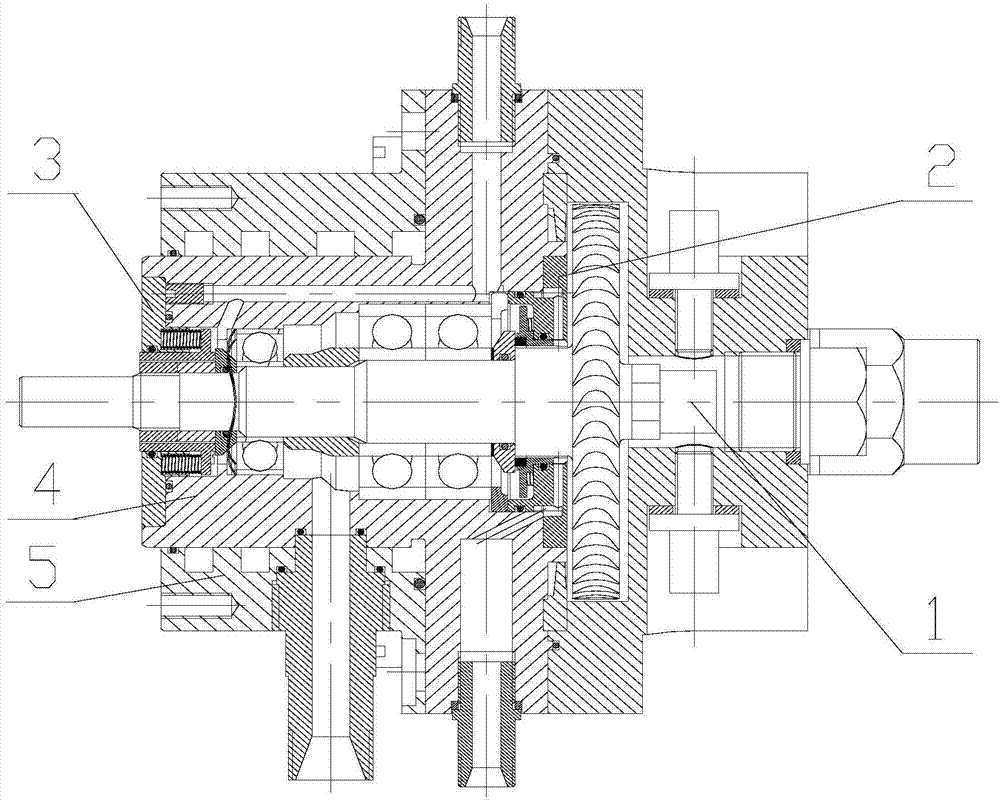
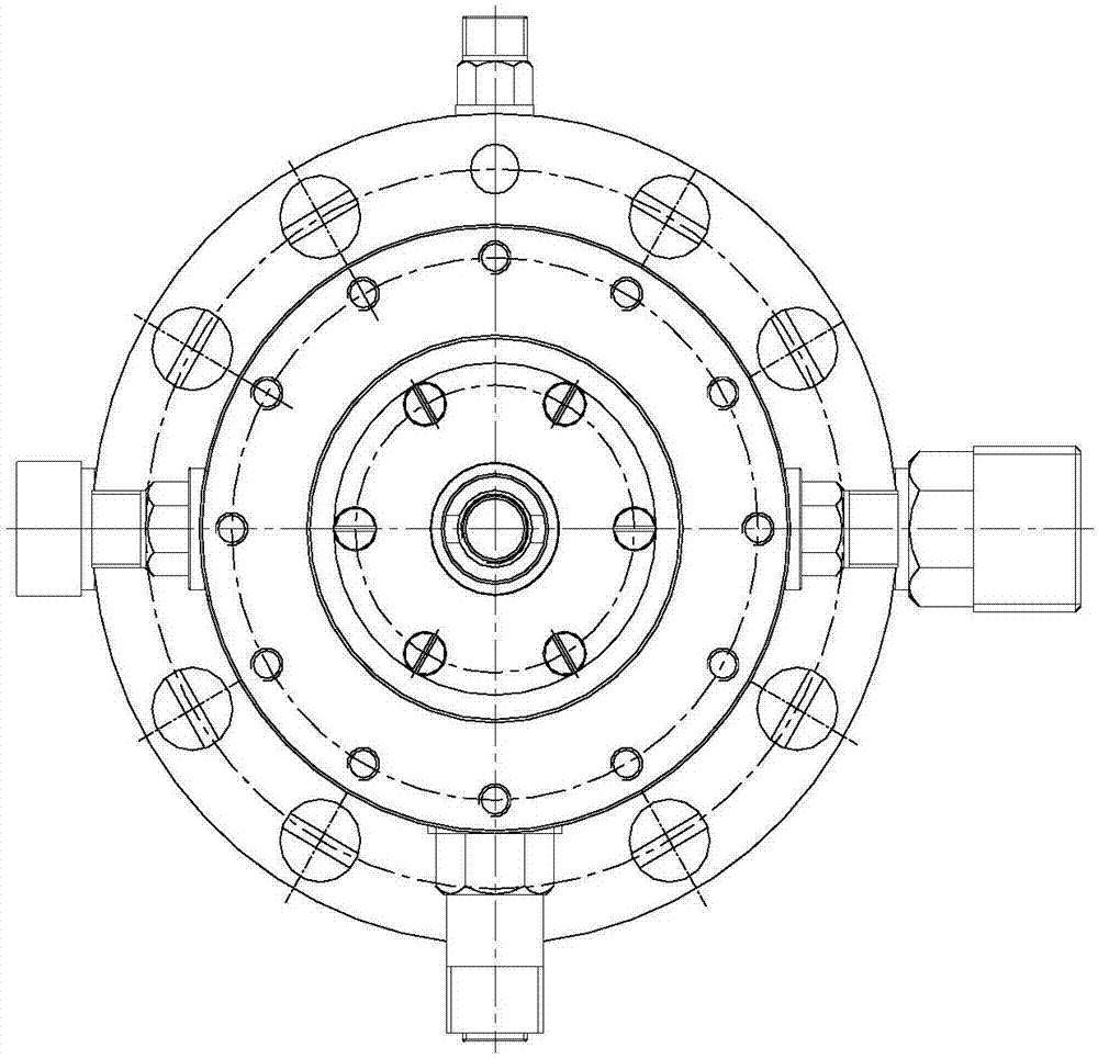
[0043] Such as figure 1 and figure 2 As shown, the present invention provides an ultra-high-speed turbine suitable for high-temperature and high-pressure working medium, including a turbine shaft assembly 1, a high-temperature mechanical seal assembly 2, a low-temperature mechanical seal assembly 3, a housing assembly 4, and a cooling water jacket assembly 5; The turbine shaft assembly 1 passes through and is installed inside the casing assembly 4, the high temperature mechanical seal assembly 2 is located inside the casing assembly 4 and connected with the turbine shaft assembly 1, and the low temperature mechanical seal assembly 3 is installed inside the casing assembly 4 and connected to the turbine shaft assembly 1. The shaft ...


PUM


Abstract

The invention belongs to the technical field of turbines, and in particular, relates to a ultrahigh-speed turbine suitable for a high-temperature and high-pressure environment. The ultrahigh-speed turbine comprises a turbine shaft system module, a high-temperature mechanical sealing module, a low-temperature mechanical sealing module, a shell module and a cooling water jacket module; the turbine shaft system module penetrates through and is mounted in the shell module; the high-temperature mechanical sealing module is positioned in the shell module, and is connected with the turbine shaft system module; the low-temperature mechanical sealing module is mounted in the shell module, and is connected with the turbine shaft system module; and the cooling water jacket module is mounted at the external of the shell module. The ultrahigh-speed turbine can finish conversion from heat energy of a fluid to power of a ultrahigh-speed mechanical shaft under special working medium effect, and is used for driving a generator, a compressor, a centrifugal pump and other rotating mechanical devices.

Description

technical field [0001] The invention belongs to the technical field of turbines, and in particular relates to an ultra-high-speed turbine suitable for high-temperature and high-pressure working medium. Background technique [0002] In the existing small turbine structure, the intake nozzles are basically fixed and cannot be adjusted, and the output power is relatively single under specific air source pressure conditions; and the mechanical dynamic seal in the turbine structure has no external cooling medium, and the temperature rise of the sealing friction pair is fast, and the resistance The wearability is poor, which makes it difficult for the turbine to be suitable for high-temperature and high-pressure working medium; at the same time, during the high-temperature working medium and long-term working process of the turbine, the heat generated by the bearing operation is not easy to dissipate, which leads to the deterioration of the working environment of the bearing and th...

Claims


Application Information

Patent Timeline
IPC IPC(8): F01D11/00F01D11/04F01D25/12F01D25/16F01D9/04F01D25/18
CPCF01D9/04F01D11/003F01D11/04F01D25/12F01D25/125F01D25/16F01D25/18
Inventor 郝小龙胡丽国宋满存王志峰李振将
Owner BEIJING RES INST OF PRECISE MECHATRONICS CONTROLS
Why Eureka
Try Eureka