
Oil-electricity dual-power mixed-flow pump

A dual-power, mixed-flow pump technology, applied to the frame of the engine, the pump, the components of the pumping device for elastic fluid, etc., can solve the problems of slow energy collection, collision with the inner wall of the base, and low protection performance, so as to improve the use Long life, easy to dock and stable, good protection performance

Inactive Publication Date: 2018-05-08
高邮市大江泵业有限公司
View PDF1 Cites 1 Cited by
  • Summary
  • Abstract
  • Description
  • Claims
  • Application Information

AI Technical Summary

Problems solved by technology

[0004] 1. The protection performance is low. The power supply is installed in the inner cavity of the base without a protection device. It is easy to shake and collide with the inner wall of the base on the bumpy road in the field, which will seriously affect the service life of the power supply and also affect the field work process;
[0005] 2. The energy conversion rate is low. The solar panel is installed horizontally on the ceiling and cannot be adjusted to rotate with the sun, resulting in too slow energy collection, making it difficult to charge the power supply in time, and it is easy to fail to work due to insufficient power. If the diesel engine is always used to maintain work , which will consume a large amount of diesel oil, which will not only pollute the environment, but also increase the work cost. Therefore, we propose a mixed-flow pump with dual power of oil and electricity

Method used


Image

  • Oil-electricity dual-power mixed-flow pump
  • Oil-electricity dual-power mixed-flow pump
  • Oil-electricity dual-power mixed-flow pump

Examples


Embodiment Construction

[0021] The following will clearly and completely describe the technical solutions in the embodiments of the present invention with reference to the accompanying drawings in the embodiments of the present invention. Obviously, the described embodiments are only some, not all, embodiments of the present invention. Based on the embodiments of the present invention, all other embodiments obtained by persons of ordinary skill in the art without making creative efforts belong to the protection scope of the present invention.

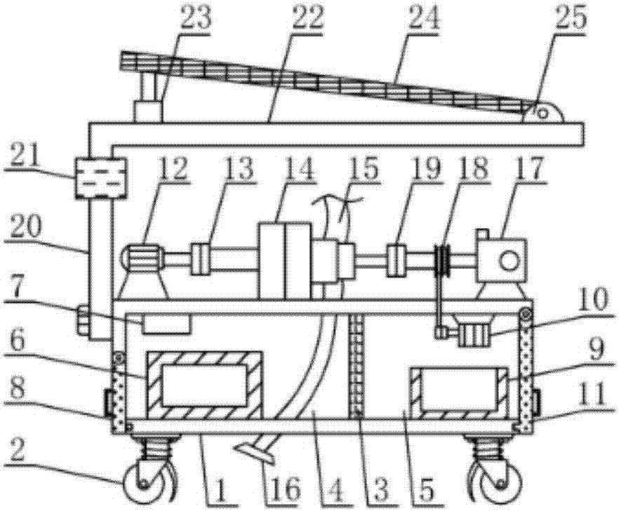
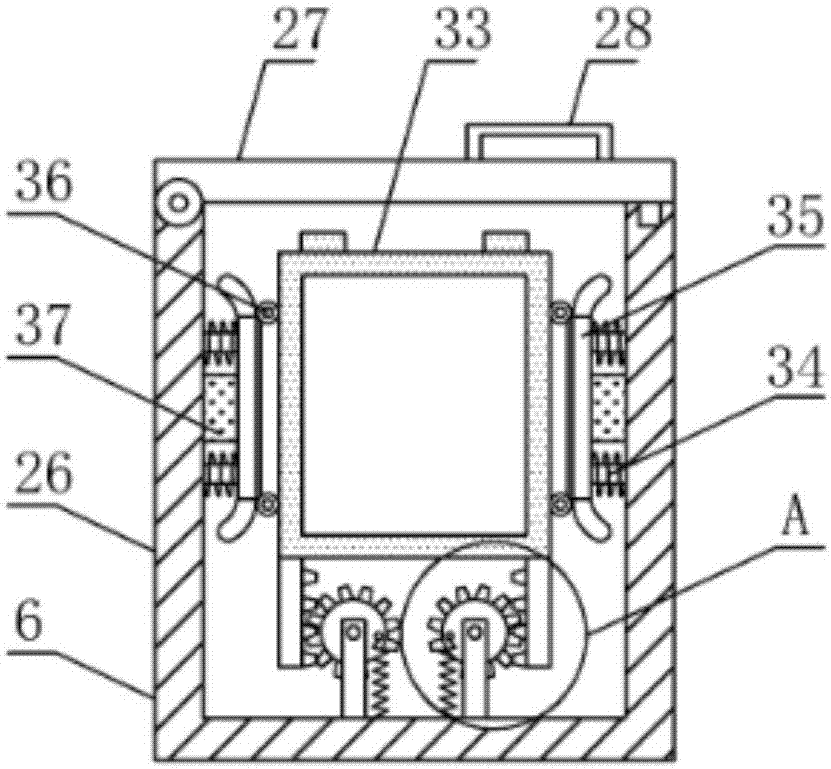
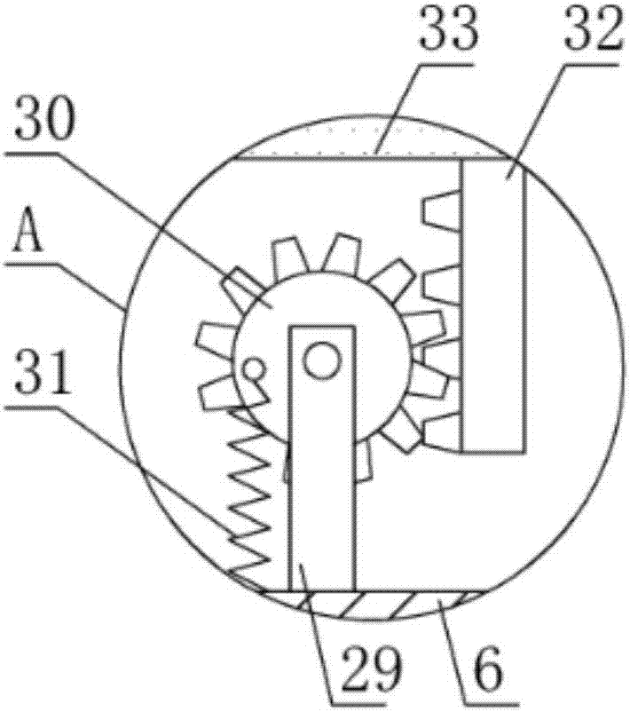
[0022] see Figure 1-3 , the present invention provides a technical solution: an oil-electric dual-power mixed-flow pump, including a base 1, and the four corners of the bottom of the base 1 are equipped with walking wheels 2, which effectively improve the mobility and stability of the device. The base 1 is provided with a rectangular The inner cavity, and the rectangular inner cavity is divided into the left energy storage chamber 4 and the right toolbox cham...


PUM


Abstract

The invention discloses an oil-electricity dual-power mixed-flow pump, and belongs to the technical field of mixed-flow pumps. The mixed-flow pump comprises a base; walking wheels are arranged at fourcorners of the bottom of the base; a rectangular inner cavity is formed in the base; a diesel engine is arranged at the right end of the top of the base; an electric telescopic rod is arranged at theleft end of the top of a ceiling; and the other end of a solar panel is hinged to the right side of the top of the ceiling through a rotating shaft. The mixed-flow pump has the advantages that the protection performance is good, damping rods are matched with damping blocks so that the stability of an energy storage battery can be effectively improved, pulleys are attached to the outer wall of theenergy storage battery so that the energy storage battery can be conveniently protected, the energy storage battery can be prevented from colliding with the inner wall of a protective shell, the topof a stand column is connected to the ceiling through a bearing so that the horizontal position of the solar panel can be conveniently adjusted, the electric telescopic rod can adjust the inclinationangle of the solar panel so that the conversion rate of the solar panel can be effectively increased, and the walking wheels are universal walking wheels so that the mobility of the pump can be effectively improved.

Description

technical field [0001] The invention relates to the technical field of mixed-flow pumps, in particular to an oil-electric dual-power mixed-flow pump. Background technique [0002] Mixed-flow pumps use the centrifugal force and thrust generated by the rotation of the impeller to work together, with oblique flow, also known as diagonal-flow pumps. There are two types: worm (horizontal) and guide vane (vertical). The specific speed of the mixed-flow pump is higher than that of the centrifugal pump and lower than that of the axial-flow pump, generally between 300-500. Most of the existing mixed-flow pumps are installed on the base, and they do not have the function of movement. When in use, they cannot move and change positions in a short distance in time according to the needs. When moving, they need to be transported by vehicle and a lot of manpower. The transport is time-consuming, laborious, and very inconvenient; , most of the existing mixed-flow pumps are single-power, wh...

Claims


Application Information

Patent Timeline
Patent Type & Authority Applications(China)
IPC IPC(8): F04D13/02F04D13/06F04D29/00H02S20/30F16M3/00
CPCF04D13/02F04D13/06F04D13/068F04D29/007F16M3/00H02S20/30Y02E10/50
Inventor 徐祝山徐鹏程
Owner 高邮市大江泵业有限公司
Learn More