Automatic lubricating oil filling device
An automatic filling and lubricating oil technology, which is applied in the direction of engine lubrication, engine components, mechanical equipment, etc., can solve the problems of decreased accuracy and stability, damage to the lubrication environment, and poor lubrication characteristics of guide rails, and achieves reasonable structure and supply The oil is stable to ensure the effect required for real-time lubrication
- Summary
- Abstract
- Description
- Claims
- Application Information
AI Technical Summary
Problems solved by technology
Method used
Image

Examples
Embodiment 1
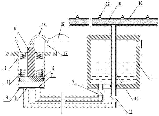
[0017] as attached figure 1 As shown, a lubricating oil automatic filling device includes an oil storage chamber 1, a suction pump, the suction pump includes a pump body 2, the pump body is provided with an upper end cover 3 and a lower end cover 4, and the pump body is provided with a piston 5, The edge of the piston 5 is in sealing contact with the inner wall of the pump body 2 , the piston 5 is connected to the piston rod 6 , and the top of the piston rod 6 passes through the upper end cover 3 .
[0018] as attached figure 1 As shown, a suction hole 7 and a discharge hole 8 are respectively provided on the lower end cover 4 of the pump body.
[0019] as attached figure 1 As shown, the suction hole 7 is connected to the oil storage chamber 1 through a pipeline, and a first one-way valve 9 is provided on the connecting pipeline, and the discharge hole 8 is connected to the fuel injection pipe 10 through a pipeline, and in this connection A second one-way valve 11 is provid...
Embodiment 2
[0028] This embodiment is further improved on the basis of Embodiment 1.
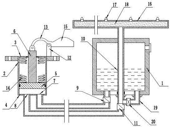
[0029] In the lubricating oil filling device provided in Embodiment 1, when the piston rod 6 moves up and down with the movement of the slider, the oil injection pipe 10 continues to inject oil, and in some application environments, it is not required The continuous filling of lubricating oil requires that the lubricating oil form the effect of time-sharing filling, that is, although the piston rod 6 is in a state of continuous reciprocating motion, the oil injection pipe 10 does not spray oil continuously, but sprays oil in a controlled time-sharing manner. . In order to achieve the above effects, in this embodiment, as attached figure 2 As shown, on the basis of the lubricating oil filling device provided in Embodiment 1, a branch pipe 19 is provided on the pipeline connecting the discharge hole 8 and the oil injection pipe 10, and the branch pipe 19 connects the connected pipeline with the oil stor...
Embodiment 3
[0031] In this embodiment, the driving device at the top of the piston rod 6 provided in Embodiment 1 is further limited.
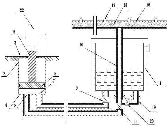
[0032] as attached image 3 As shown, in this embodiment, the driving device at the top of the piston rod 6 can be an electric driving device. In this embodiment, the electric driving device is driven by an electric push rod 22. After the electric push rod 22 is used for driving, The support spring 14 in Embodiment 1 can be removed, and the timing control of lubricating oil injection can also be realized by controlling the action interval of the electric push rod 22 .
[0033] Of course, in addition to the electric push rod provided in this embodiment, the electric drive device can also use a motor to drive the screw or other electric drive devices that can drive the piston to move up and down, which will not be described in detail here.
[0034] The use of an electric drive device can separate the drive device from moving parts such as sliding blocks, w...
PUM
 Abstract
Description
Claims
Application Information
 - R&D
- Intellectual Property
- Life Sciences
- Materials
- Tech Scout
- Unparalleled Data Quality
- Higher Quality Content
- 60% Fewer Hallucinations
Browse by: Latest US Patents, China's latest patents, Technical Efficacy Thesaurus, Application Domain, Technology Topic, Popular Technical Reports.
© 2025 PatSnap. All rights reserved.Legal|Privacy policy|Modern Slavery Act Transparency Statement|Sitemap|About US| Contact US: help@patsnap.com