Supercharge Your Innovation With Domain-Expert AI Agents!

CCD-based pendulum mirror linearity test system

A testing system and linearity technology, applied in the direction of measuring devices, instruments, and optical devices, can solve the problems of limited scale accuracy, inconvenient testing, and limited accuracy, so as to improve the imaging effect, avoid imaging blur and sawtooth phenomenon, The effect of imaging effect optimization

Inactive Publication Date: 2018-05-08
北京长峰科威光电技术有限公司
View PDF10 Cites 7 Cited by
  • Summary
  • Abstract
  • Description
  • Claims
  • Application Information

AI Technical Summary

Problems solved by technology

The former method is simple, but the feedback signal reflects the position of the motor, which cannot directly reflect the linearity of the oscillating mirror, especially in the area where the oscillating mirror is far away from the motor axis, and the accuracy is limited
The method of measuring the laser projection reflected by optical scanning on the scale can directly and intuitively reflect the linearity of the pendulum mirror, but the accuracy of the scale is limited, and the entire system takes up a large space, requiring manual participation, which is inconvenient to test and cannot be compared with The whole system forms a closed loop

Method used


Image

  • CCD-based pendulum mirror linearity test system
  • CCD-based pendulum mirror linearity test system
  • CCD-based pendulum mirror linearity test system

Examples


Embodiment Construction

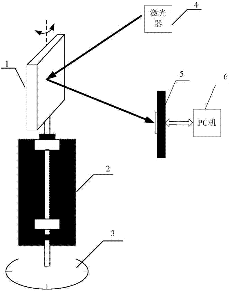
[0011] Such as figure 1 As shown, the CCD-based swing mirror linearity test system mainly includes swing mirror 1, motor 2, photoelectric encoder 3, laser 4, linear array image sensor (CCD) 5, PC 6; the output of swing mirror 1 and motor 2 One end of the shaft is connected, and the other end of the output shaft of the motor 2 is connected to the photoelectric encoder 3; the laser incident direction of the laser 4 is perpendicular to the rotation axis of the swing mirror 1, the reflected light of the swing mirror is parallel to the photosensitive element line of the CCD, and the output circuit of the CCD5 passes through The serial port communicates with the PC 6 .

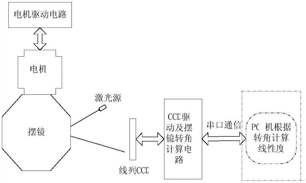
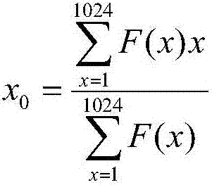
[0012] Such as figure 2 As shown, the CCD is used to receive the reflected light of the swing mirror to obtain a series of spot signals. The CCD converts the collected spot signals into analog electrical signals. After AD conversion, the output is sent to the CCD drive circuit for calculation, and the coordinates ...


PUM


Abstract

A CCD-based pendulum mirror linearity test system includes a pendulum mirror, a motor, a photoelectric encoder laser, a CCD, and a PC. The pendulum mirror is connected to one end of an output shaft ofthe motor, and the other end of the output shaft of the motor is connected with the photoelectric encoder. The motor drives the pendulum mirror to rotate, the laser emits a light source to illuminatethe pendulum mirror, the CCD receives the reflected light of the pendulum mirror, obtains a series of spot signals, and outputs to a CCD drive circuit through AD conversion, and the coordinate information of each spot is calculated. Meanwhile, the CCD reads angle information of the pendulum mirror through the photoelectric encoder, calibrates an angle value corresponding to the center of each spot and outputs the angle value to the PC, the measured angle value is compared with a perfectly linear ideal angle value to obtain the difference between the measured angle value and the ideal angle value, and thus, the linearity of the pendulum mirror is calculated.

Description

technical field [0001] The invention relates to the field of optoelectronic technology, in particular to a CCD-based swing mirror linearity test system, which is mainly used in the test of the swing mirror linearity of the scanning imaging system and the optimization of the scanning imaging system. Background technique [0002] At present, the commonly used methods for testing the linearity of the pendulum mirror in scanning imaging systems are mainly divided into two categories, one is indirect testing through the feedback signal in the motor, and the other is measuring on the scale by optically scanning reflected laser projection. The former method is simple, but the feedback signal reflects the position of the motor and cannot directly reflect the linearity of the oscillating mirror, especially in the area where the oscillating mirror is far away from the motor axis, and the accuracy is limited. The method of measuring the laser projection reflected by optical scanning on...

Claims


Application Information

Patent Timeline
Patent Type & Authority Applications(China)
IPC IPC(8): G01B11/26
CPCG01B11/26
Inventor 周培涛
Owner 北京长峰科威光电技术有限公司
Features
  • R&D
  • Intellectual Property
  • Life Sciences
  • Materials
  • Tech Scout
  • Unparalleled Data Quality
  • Higher Quality Content
  • 60% Fewer Hallucinations
Learn More