Broadband dielectric resonator

A dielectric resonator and resonator technology, applied in the microwave field, can solve problems such as limiting available broadband, achieve easy identification, improve measurement speed and accuracy, and have obvious suppression effects

Active Publication Date: 2018-05-08
UNIV OF ELECTRONICS SCI & TECH OF CHINA
View PDF8 Cites 3 Cited by
  • Summary
  • Abstract
  • Description
  • Claims
  • Application Information

AI Technical Summary

Problems solved by technology

But despite this, there are still a large number of interference modes in the working frequency band, which severely limits the available bandwidth. Therefore, how to suppress the interference mode as much as possible without affecting the working mode to obtain a relatively pure TE 0np mode, which has become a key problem in the design of dielectric resonator method to measure complex permittivity

Method used


Image

  • Broadband dielectric resonator
  • Broadband dielectric resonator
  • Broadband dielectric resonator

Examples


Embodiment Construction

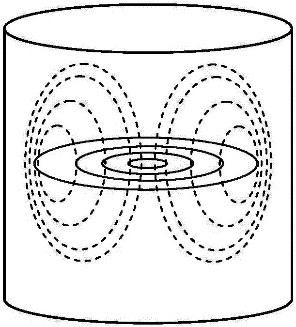
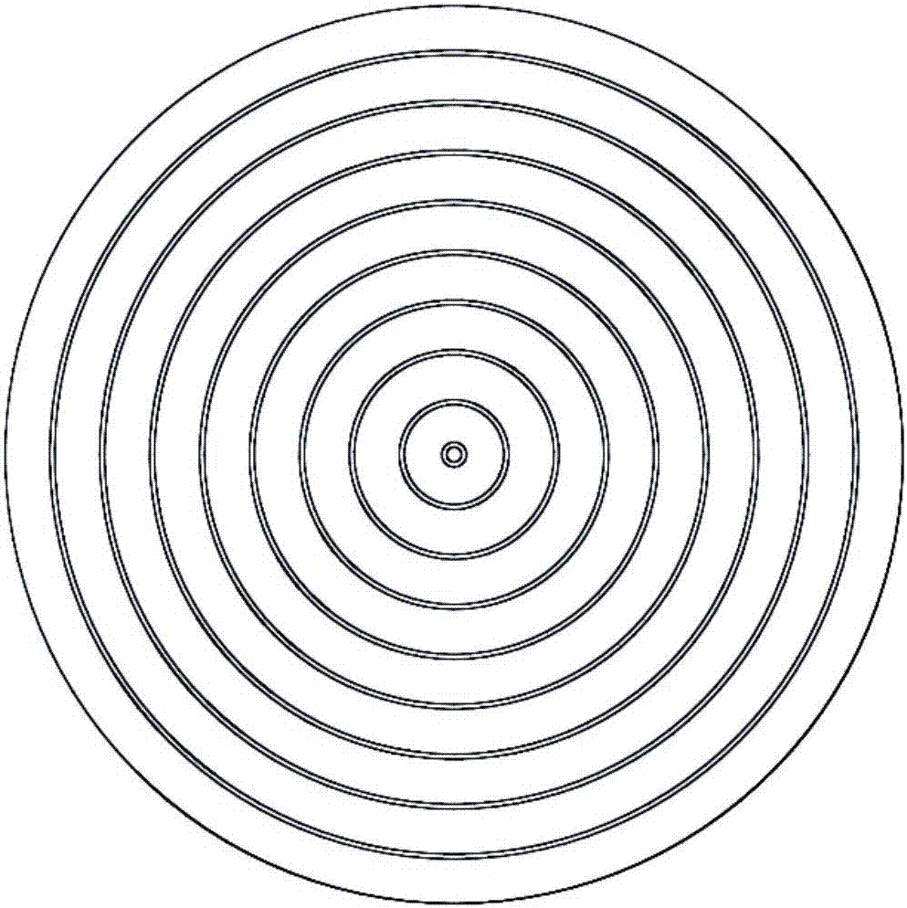
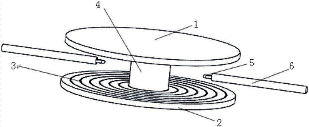
[0029] A broadband dielectric resonator, such as figure 2 , image 3As shown, it includes the upper plate 1 of the resonator, the lower plate 2 of the resonator, and the dielectric material 4 to be tested and two coupling rings 5 ​​between the upper and lower plates of the resonator. The dielectric material to be tested is pressed by the upper and lower plates of the resonator. Tight, the upper and lower plates of the resonator and the dielectric material to be tested constitute a dielectric resonance part; the upper and lower plates of the resonator are parallel to each other and are made of a circular hard dielectric substrate; the dielectric material to be tested is Vertical to the cylinder at the center of the upper and lower plates of the resonator, two coupling rings are distributed on both sides of the dielectric material to be tested along the diameter direction of the upper and lower plates of the resonator and point to the center of the circle, the upper and lower p...


PUM


Abstract

The invention provides a broadband dielectric resonator. The broadband dielectric resonator comprises an upper plate and a lower plate of the resonator, a dielectric material to be detected and a coupling ring, wherein the upper plate and the lower plate of the resonator and the dielectric material to be detected form a dielectric resonance part; the upper plate and the lower plate of the resonator are manufactured from a hard dielectric substrate; a metal coating is arranged on the surface, facing the dielectric material to be detected, of the hard dielectric substrate, and a gap structure iscarved in the metal coating. Through the adoption of the scheme, most parasitic modes can be inhibited effectively, so that the operating mode is identified more easily, particularly in high band ofthe operating mode, the inhibitory effect for parasitic modes is more obvious, and finally a relatively pure TE0np mode frequency spectrum can be obtained in a wide frequency range.

Description

technical field [0001] The invention belongs to the field of microwave technology, in particular to a TE for complex permittivity testing 0np Mode broadband dielectric resonator. Background technique [0002] TE 0np The mode dielectric resonator is a microwave resonator, which can be used for the measurement of the complex permittivity of dielectric materials and the measurement of microwave broadband conductivity. This technology has the characteristics of fast, reliable, accurate, non-destructive, and automatic measurement. practicality. It works in TE mode, and has the advantages of simple field structure, stability, no dispersion, wide operating frequency and so on. A common dielectric resonator consists of two upper and lower metal covers and a circular dielectric material to be tested. The coupling ring is used to excite the strongest magnetic field on both sides of the dielectric material to be tested to make it resonate. Different n and p can be selected to obtai...

Claims


Application Information

Patent Timeline
Patent Type & Authority Applications(China)
IPC IPC(8): H01P7/10
CPCH01P7/10
Inventor 龙嘉威李恩余承勇张云鹏李亚峰高冲高勇郑虎
Owner UNIV OF ELECTRONICS SCI & TECH OF CHINA
Why Eureka
Try Eureka