Turning conveying device

A transmission device and power technology, applied in the direction of lifting devices, etc., can solve the problems of unsatisfactory market promotion and application, complex structure of reversing transmission equipment, interruption of continuous transmission, etc., to avoid mechanical misoperation, simple structure and stable operation Effect

Pending Publication Date: 2018-05-11
张青云
View PDF0 Cites 0 Cited by
  • Summary
  • Abstract
  • Description
  • Claims
  • Application Information

AI Technical Summary

Problems solved by technology

The existing assembly line conveyor chain is generally linear conveying. When the product needs to be transported in a different direction during the processing process or when the finished product reaches the end of the assembly line, it needs to be transported by a forklift, resulting in the interruption of continuous conveying.
[0003] At present, the direction-changing transmission equipment installed in the pipeline conveyor chain is complex in structure, expensive, and has poor versatility, so the market promotion and application is not very ideal

Method used


Image

  • Turning conveying device
  • Turning conveying device
  • Turning conveying device

Examples


Embodiment Construction

[0020] The structure and working principle of a direction-changing transmission device provided by the present invention will be further described in detail below in conjunction with the accompanying drawings.

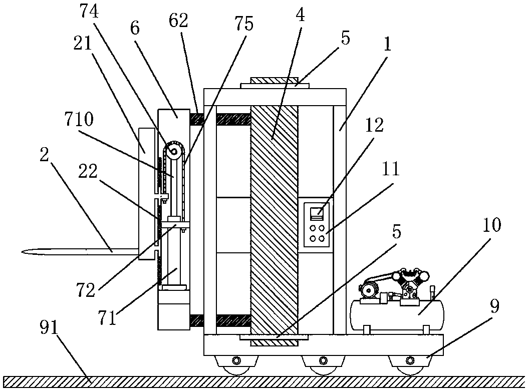
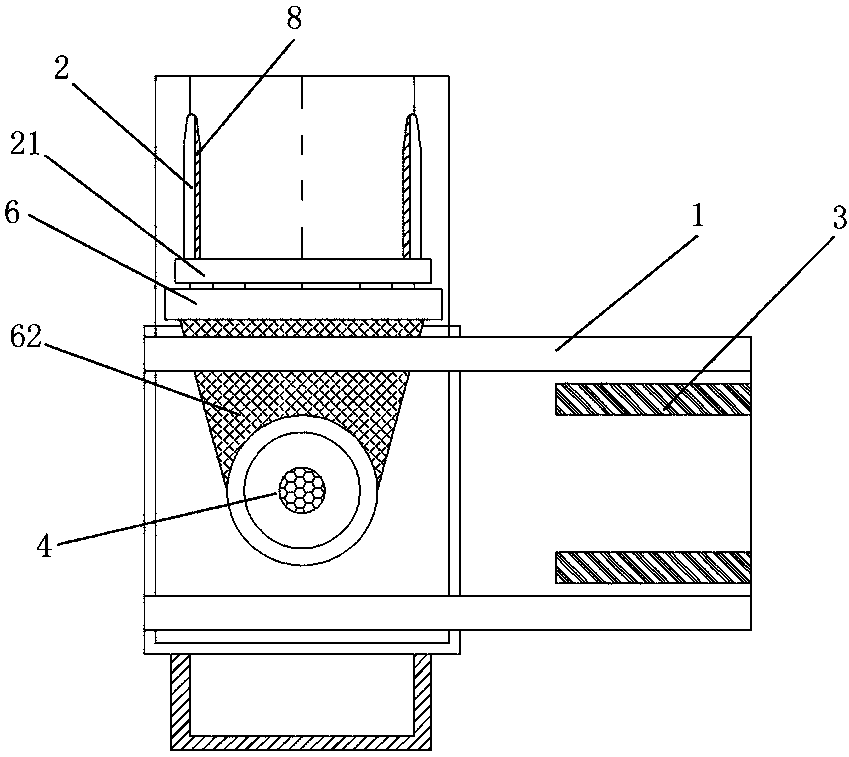
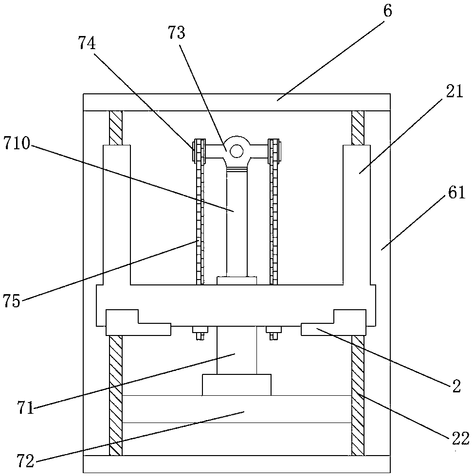
[0021] like figure 1 As shown, it is a structural schematic diagram of a variable transmission and transmission device provided by the present invention. The structure constituting the reversing transmission device is mainly composed of a frame 1, a rotatable lifting fork 2 arranged at one end of the frame 1, and a receiving arm 3 arranged at the other end of the frame 1, wherein the lifting fork 2 Driven to rotate by the power shaft 4 arranged inside the frame 1 , the power shaft 4 is fixed in bearing seats 5 provided on the top and bottom of the frame 1 .

[0022] Its working principle is: after the material arrives, start the lifting fork 2 to lift the material, and the power shaft 1 drives the lifting fork 2 to rotate along the preset direction-changing angle to c...


PUM


Abstract

The invention belongs to the technical field of conveying equipment, and particularly relates to a turning conveying device. According to the main technical scheme of the turning conveying device, theturning conveying device is mainly composed of a rack, a lifting fork and a bearing arm, wherein the lifting fork is arranged at one end portion of the rack and can rotate, and the bearing arm is arranged at the other end portion of the rack. The lifting fork is driven by a power rotation shaft arranged in the rack to rotate. The power rotation shaft is fixed into bearing blocks arranged on the top face and the bottom face of the rack. A cleaning device has the beneficial effects of being simple in structure, convenient to operate and capable of achieving automatic turning conveying.

Description

technical field [0001] The invention belongs to the technical field of conveying equipment, and in particular relates to a direction-changing conveying device. Background technique [0002] With the continuous improvement of the level of mechanization, more and more enterprises adopt the assembly line conveyor chain for large-scale production, which solves the defects of excessive consumption of manpower and mechanical resources in the links of material transportation and finished product loading and unloading. The existing assembly line conveyor chain is generally linear conveying. When the product needs to be transported in a different direction during the processing process or when the finished product reaches the end of the assembly line, it needs to be transported by a forklift, resulting in the interruption of continuous conveying. [0003] Currently, the direction-changing transmission equipment installed in the assembly line conveyor chain has a complex structure, is...

Claims


Application Information

Patent Timeline
Patent Type & Authority Applications(China)
IPC IPC(8): B66F9/12B66F9/20B66F9/075
CPCB66F9/12B66F9/07504B66F9/0755B66F9/20
Inventor 张青云
Owner 张青云
Why Eureka
Try Eureka