
Automobile lamp PES unit, automobile lamp assembly and automobile

A technology of car lights and reflectors, which is applied in the direction of headlights, motor vehicles, road vehicles, etc., can solve the problems of poor light energy utilization rate, poor road surface illumination, inability to effectively emit light, and inability to be used, so as to improve road surface illumination The effect of ensuring the heat dissipation performance of the light source, increasing the brightness of the irradiation and the effect of the effective irradiation distance

Pending Publication Date: 2018-05-11
HASCO VISION TECHNOLOGY CO LTD
View PDF4 Cites 0 Cited by
  • Summary
  • Abstract
  • Description
  • Claims
  • Application Information

AI Technical Summary

Problems solved by technology

[0004] Due to the design of the traditional car light PES unit with a single LED light source, the light emitted to form the illumination light pattern is all emitted from a lens 03, so the visual effect formed is that only a single light source emits light
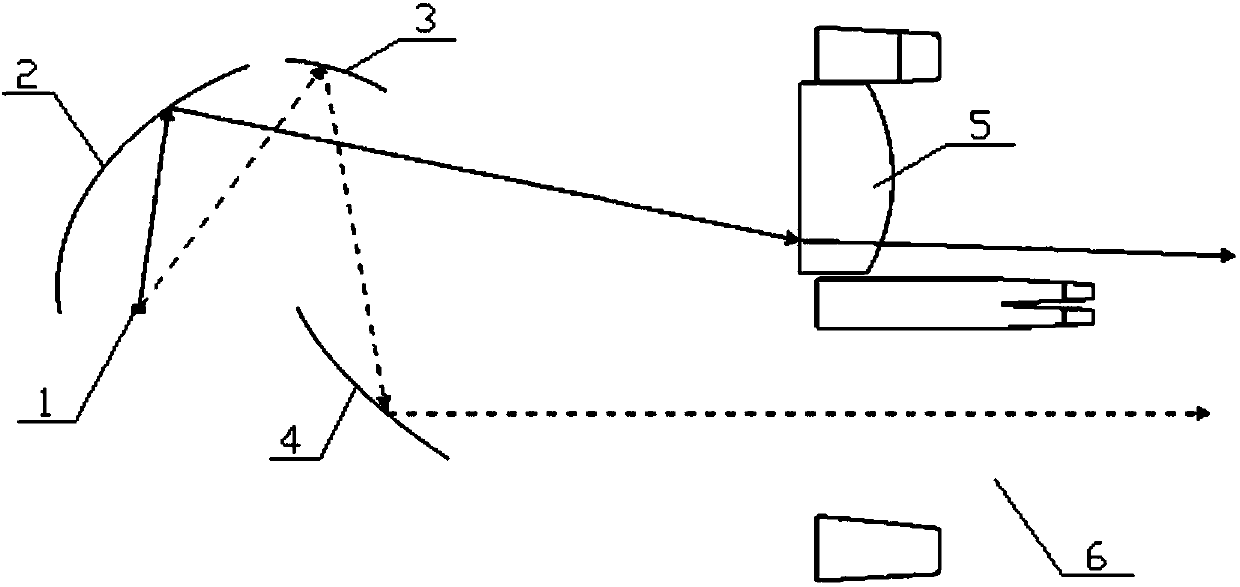
Moreover, due to the small size requirement of the lens 03, only part of the light emitted by the LED light source 01 can be projected onto the lens 03 to form an effective output ( figure 1 The light shown by the solid line with the arrow in the center), there are also some light rays that are not projected on the lens 03 and cannot be effectively emitted ( figure 1 The light shown by the dotted line with the arrow in the middle), becomes the afterglow that cannot be used, resulting in poor light energy utilization and poor road surface illumination
If these defects are improved by increasing the number of LED light sources or using high-power LED light sources, the heat distributed around the LED light sources will increase, resulting in attenuation of light efficiency and increased costs.

Method used


Image

  • Automobile lamp PES unit, automobile lamp assembly and automobile
  • Automobile lamp PES unit, automobile lamp assembly and automobile
  • Automobile lamp PES unit, automobile lamp assembly and automobile

Examples


Embodiment Construction

[0026] The specific implementation manners of the present invention will be described in further detail below in conjunction with the accompanying drawings. These embodiments are only used to illustrate the present invention, not to limit the present invention.

[0027] In the description of the present invention, it should be noted that the terms "center", "longitudinal", "transverse", "upper", "lower", "front", "rear", "left", "right", " The orientations or positional relationships indicated by "vertical", "horizontal", "top", "bottom", "inner", "outer", etc. are based on the orientation or positional relationships shown in the drawings, and are only for the convenience of describing the present invention and simplifying Describes, but does not indicate or imply that the device or element referred to must have a specific orientation, be constructed in a specific orientation, and operate in a specific orientation, and therefore should not be construed as limiting the inventio...


PUM


Abstract

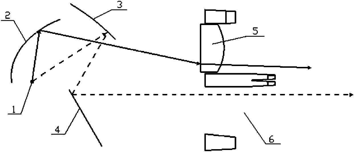
The invention relates to the technical field of an automobile lamp, in particular to an automobile lamp PES unit, an automobile lamp assembly comprising the automobile lamp PES unit and an automobilecomprising the automobile lamp assembly. The automobile lamp PES unit comprises a light source, a primary mirror, a first auxiliary mirror, a second auxiliary mirror and a lens. A light outlet is formed under the lens, and the light source is arranged at the perifocus of the primary mirror. The light emitted by the light source comprises main output light and residual light, the main output lightis reflected by the primary mirror and is projected onto the lens, and the residual light is not projected onto the lens. The first auxiliary mirror is arranged on the light path of the residual light, and the second auxiliary mirror is opposite to the first auxiliary mirror. The residual light is reflected by the first auxiliary mirror and the second auxiliary mirror successively and then is shotout from the light outlet. On the precise that the quantity of the light source and the power are not increased, the visual effect of multiple light sources is realized through a single light source,the lighting effect is improved, and the irradiation brightness and the effective irradiation distance are increased.

Description

technical field [0001] The invention relates to the technical field of automobile lamps, in particular to an automobile lamp PES unit, an automobile lamp assembly including the automobile lamp PES unit and an automobile including the automobile lamp assembly. Background technique [0002] At present, the PES unit of car lights has been widely used in the field of automotive lighting because of its small size, high energy utilization rate, uniform light pattern, and clear cut-off line. For example, the patent application with the publication number: CN105570794A discloses a PES unit with integrated LED far and near light for a car lamp and an ADB function, and specifically discloses a basic structure of the PES unit for a car lamp. [0003] The optical path design of the traditional headlight PES unit is as follows: figure 1 As shown, the LED light source 01 is set at the near focal point of the reflector 02, and the light emitted by the LED light source 01 is reflected by t...

Claims


Application Information

Patent Timeline
IPC IPC(8): F21S41/365F21W107/10F21W102/00F21Y115/10
CPCF21Y2115/10
Inventor 陈海燕陈兆禹
Owner HASCO VISION TECHNOLOGY CO LTD
Learn More