Registration-based onboard forward-looking radar clutter suppression method

A clutter suppression and radar echo technology, applied in the radar field, can solve problems such as the degradation of STAP clutter suppression performance, the non-uniformity of airborne radar echo data, and the difficulty of satisfying the conditions of independent and identically distributed samples, so as to reduce the amount of calculation, Improve real-time effect

Inactive Publication Date: 2018-05-11
XIDIAN UNIV
View PDF6 Cites 14 Cited by
  • Summary
  • Abstract
  • Description
  • Claims
  • Application Information

AI Technical Summary

Problems solved by technology

[0003] Since the statistical characteristics of clutter signals are usually unpredictable, STAP needs to select the echo data near the unit to be detected as a training sample to estimate it; in order to obtain better STAP performance (the performance loss relative to the optimal processing does not exceed 3dB ), the number of training samples required should not be less than twice the degree of freedom of the system; here it is set that the selected training samples and the data of the unit to be tested satisfy the condition of independent and identical distribution, that is, these training samples are uniform and consistent with The statistical characteristics of the unit data are the same; however, due to the complex surface types, vegetation coverage, isolated interference, water towers, tall buildings, etc. in the actual scene, airborne radars usually work in a non-uniform clutter environment; in addition, When the radar antenna is placed forward-looking, the short-range echo will have a very obvious distance dependence; these factors will lead to non-uniform airborne radar echo data, making it difficult to satisfy the independent and identically distributed sample conditions required by the above assumptions, and then It affects the estimation accuracy of the clutter covariance matrix of the unit to be detected, resulting in a serious decline in the clutter suppression performance of STAP

Method used


Image

  • Registration-based onboard forward-looking radar clutter suppression method
  • Registration-based onboard forward-looking radar clutter suppression method
  • Registration-based onboard forward-looking radar clutter suppression method

Examples


Embodiment Construction

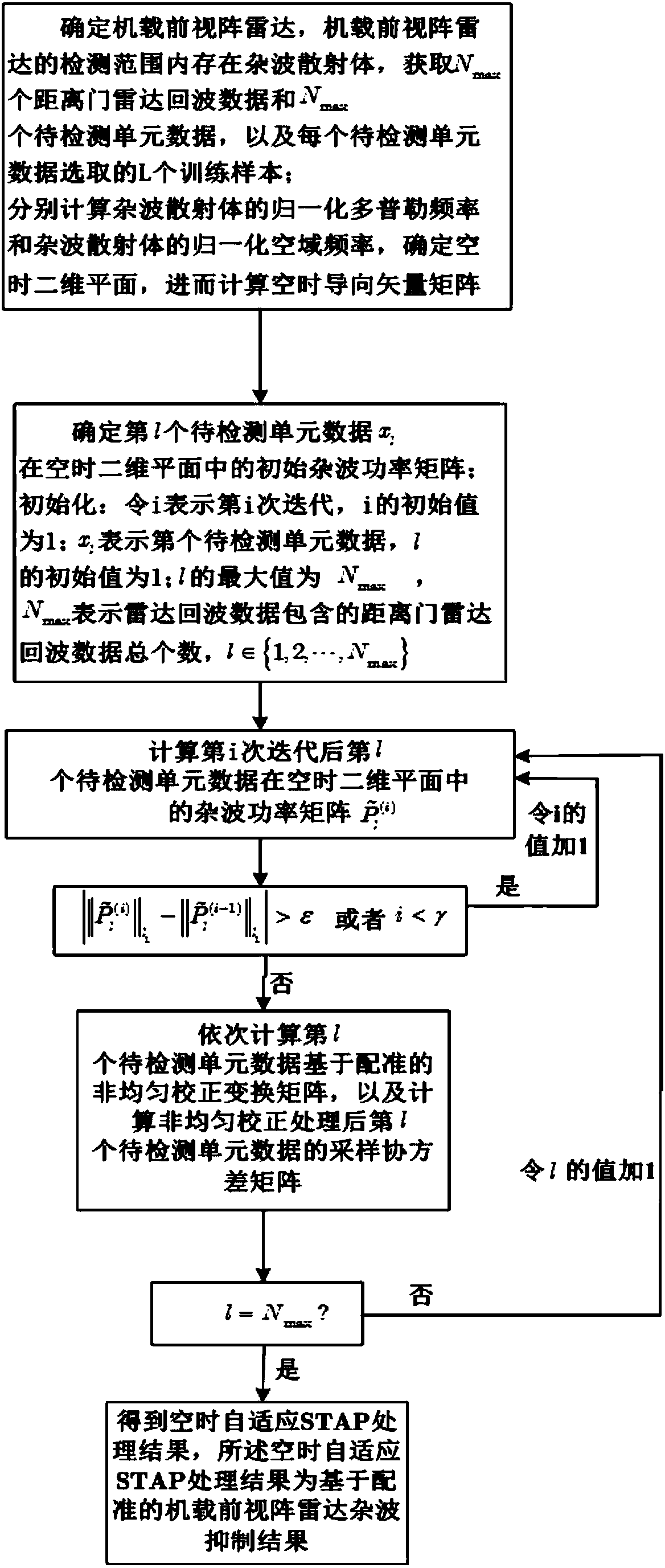
[0031] refer to figure 1 , is a flow chart of a registration-based airborne forward-looking array radar clutter suppression method of the present invention; the registration-based airborne forward-looking array radar clutter suppression method comprises the following steps:

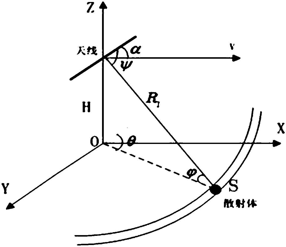
[0032] Step 1. Determine the airborne forward-looking array radar. There is a clutter scatterer S within the detection range of the airborne forward-looking array radar. Airborne forward-looking array radar unwanted echo objects.

[0033] The airborne forward-looking array radar transmits signals and receives radar echo data, and the radar echo data contains N max The radar echo data of the range gates are sequentially recorded as the radar echo data of the first range gate, the radar echo data of the second range gate, ..., the Nth max The radar echo data of each range gate; record the radar echo data of each range gate as a unit data to be detected, and then get N max unit data to be tested.

[0034...


PUM


Abstract

The invention discloses a registration-based onboard forward-looking radar clutter suppression method. The method comprises the steps of determining an onboard forward-looking radar, wherein a clutterscatterer exists within the detection range of the onboard forward-looking radar; acquiring Nmax range gate radar echo data and Nmax to-be-detected unit data, and L training samples selected for eachto-be-detected unit data; determining a space-time two-dimensional plane, a space-time steering vector matrix, and an initial clutter power matrix of a l to-be-detected unit data x in the space-time two-dimensional plane; calculating a sample covariance matrix of the l to-be-detected unit data x after the non-uniform correction treatment, setting the value of l from 1 to Nmax, and obtaining the sample covariance matrixes of to-be-detected unit data from the first to-be-detected unit data to Nmax to-be-detected unit data after the non-uniform correction treatment; respectively carrying out space-time adaptive treatment and obtaining a space-time adaptive treatment result. The space-time adaptive treatment result is a registration-based onboard forward-looking radar clutter suppression result.

Description

technical field [0001] The invention belongs to the technical field of radar, and in particular relates to a registration-based method for suppressing clutter of an airborne forward-looking array radar, which is suitable for suppressing strong ground clutter and detecting ground slow-moving targets by an airborne early warning radar in a non-uniform environment. Background technique [0002] Airborne early warning radar will inevitably be affected by complex and strong ground clutter while receiving target echo signals. How to effectively detect moving targets from the extremely strong clutter background is always the key point of airborne early warning radar signal processing. Therefore, clutter suppression has become the primary problem that must be solved; space-time adaptive processing technology can simultaneously distinguish moving targets and clutter from the two dimensions of airspace and time domain, and can effectively improve the clutter suppression and The perfor...

Claims


Application Information

Patent Timeline
Patent Type & Authority Applications(China)
IPC IPC(8): G01S7/02G01S7/292G06F17/50
CPCG01S7/023G01S7/292G06F30/20G06F2119/10
Inventor 王彤肖浩
Owner XIDIAN UNIV
Why Eureka
Try Eureka