
Umbrella antenna oscillator

An umbrella-shaped antenna and antenna vibrator technology, applied in the field of antennas, can solve the problems of large antenna size, unsightly appearance, and poor reception effect of small-sized antennas, and achieve the effect of improving receiving efficiency and reducing height and size

Pending Publication Date: 2018-05-11
GUANGDONG SHENGLU TELECOMM TECH
View PDF9 Cites 3 Cited by
  • Summary
  • Abstract
  • Description
  • Claims
  • Application Information

AI Technical Summary

Problems solved by technology

[0003] The purpose of the present invention is to provide a simple structure in order to solve the deficiencies of the prior art, which not only solves the problem that the existing antenna size is too large, resulting in unattractive installation on the car, but also solves the low-profile small-size antenna receiving Umbrella Antenna Elements for Ineffective Problems

Method used


Image

  • Umbrella antenna oscillator
  • Umbrella antenna oscillator
  • Umbrella antenna oscillator

Examples


Embodiment Construction

[0017] The technical solution will be described in detail below in conjunction with specific embodiments.

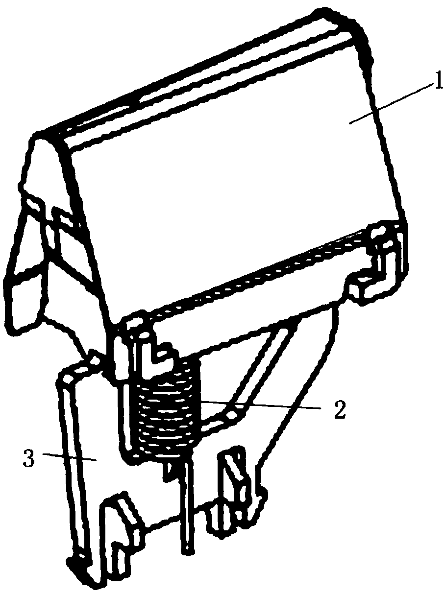
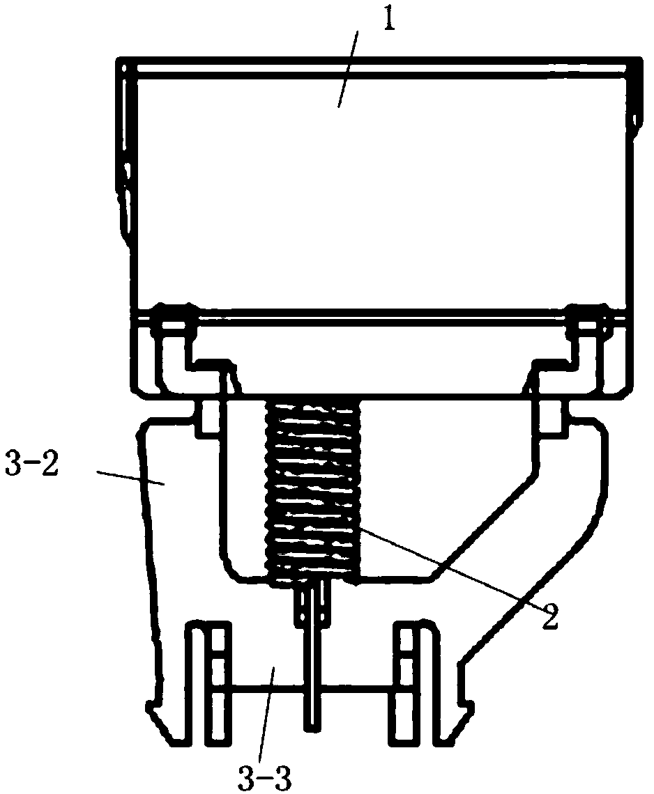
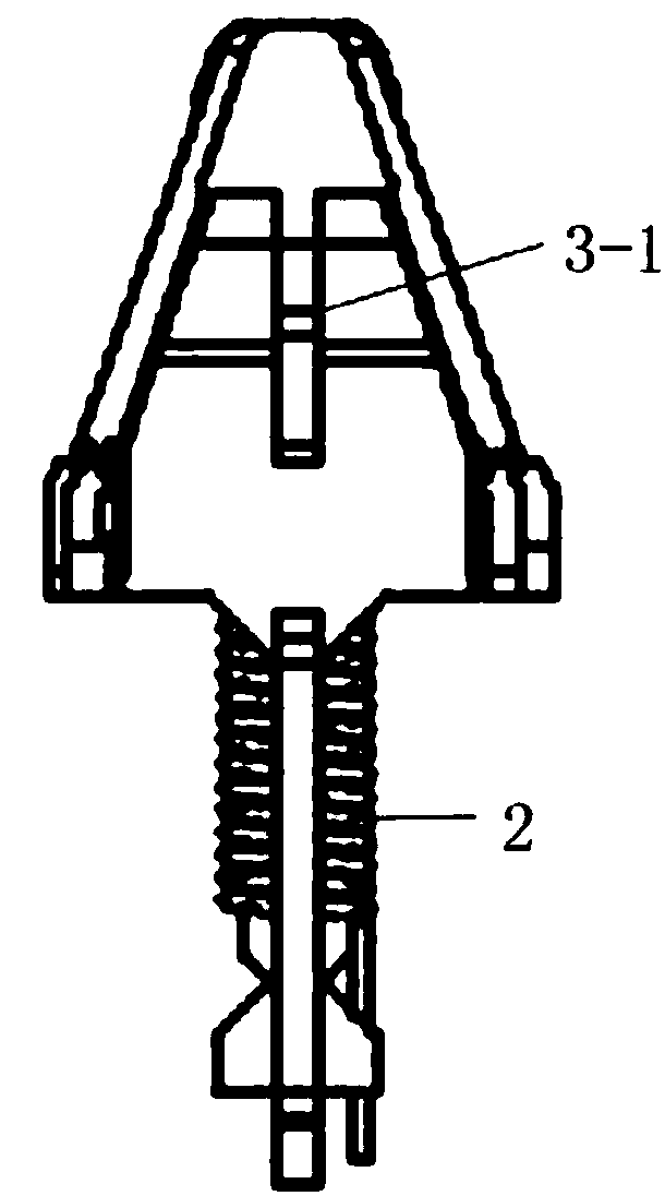
[0018] Such as Figure 1-Figure 3 As shown, the present invention is an umbrella-shaped antenna vibrator, which includes the main body of the antenna vibrator. The main body of the antenna vibrator is mainly composed of an umbrella-shaped metal sheet 1, a spiral metal winding 2 and a non-metallic bracket 3. The umbrella-shaped metal sheet and the spiral metal winding The wires are connected together, and the umbrella-shaped metal sheet is fixed on a non-metallic bracket; the umbrella-shaped metal sheet is set on the top of the main body of the antenna vibrator, forming a gap between the roof sheet metal or the metal base used to fix the main body of the umbrella-shaped antenna vibrator. The distributed capacitance structure is used as the capacitive loading on the top of the antenna; the spiral metal wire is set in the middle of the main body of the antenna oscillator, a...


PUM


Abstract

The invention discloses an umbrella antenna oscillator. The umbrella antenna oscillator is characterized by comprising an antenna oscillator main body, wherein the antenna oscillator main body mainlycomprises an umbrella metal sheet, a spiral metal winding and a non-metal support, the umbrella metal sheet and the spiral metal winding are connected, the umbrella metal sheet is fixed on the non-metal support, the umbrella metal sheet is arranged at the top of the antenna oscillator main body and is used as antenna top capacitance loading, and the spiral metal winding is arranged at a middle part of the antenna oscillator main body and is used as antenna middle part inductance loading. The umbrella antenna oscillator is simple in structure, the problems that the umbrella antenna oscillator is excessively large in antenna size and is not attractive when installed on a vehicle are solved, and the problem of poor receiving effect of a low-profile and small-size antenna is also solved.

Description

technical field [0001] The invention relates to the technical field of antennas, in particular to a vibrator structure for a vehicle-mounted broadcast receiving antenna. Background technique [0002] Most of the FM and AM radio receiving antennas used in automobiles are rod antennas with 1 / 4 wavelength in the FM radio working frequency band (generally 87.5MHz~108MHz), which are large in size and not beautiful enough to be installed on automobiles. Therefore, some automobiles For the sake of aesthetics, the FM and AM radio receiving antenna is installed in the shark-fin-shaped plastic shell on the roof, but due to national regulations, the height of the hard object protruding from the roof cannot be greater than 7cm, so the height of the radio receiving antenna inside the shark-fin shell can only be lower When the antenna vibrator is placed inside, its size is much smaller than 1 / 4 wavelength. At this time, the receiving efficiency of the antenna is low, and the gain is low. ...

Claims


Application Information

Patent Timeline
Patent Type & Authority Applications(China)
IPC IPC(8): H01Q1/36H01Q1/50
CPCH01Q1/36H01Q1/50
Inventor 李民邓志耀杨磊周建辉曾言
Owner GUANGDONG SHENGLU TELECOMM TECH
Learn More