Multiplexer

A technology of multiplexers and filters, applied in the field of multiplexers, can solve the problems of ripple in the passband and reduction of frequency band width.

Active Publication Date: 2018-05-11
MURATA MFG CO LTD
View PDF13 Cites 5 Cited by
  • Summary
  • Abstract
  • Description
  • Claims
  • Application Information

AI Technical Summary

Problems solved by technology

Therefore, when the passband of the receiving side filter overlaps with the resonant response frequency band of the longitudinally coupled elast

Method used


Image

  • Multiplexer
  • Multiplexer
  • Multiplexer

Examples


Embodiment approach

[0050] [1. Basic circuit structure of multiplexer]

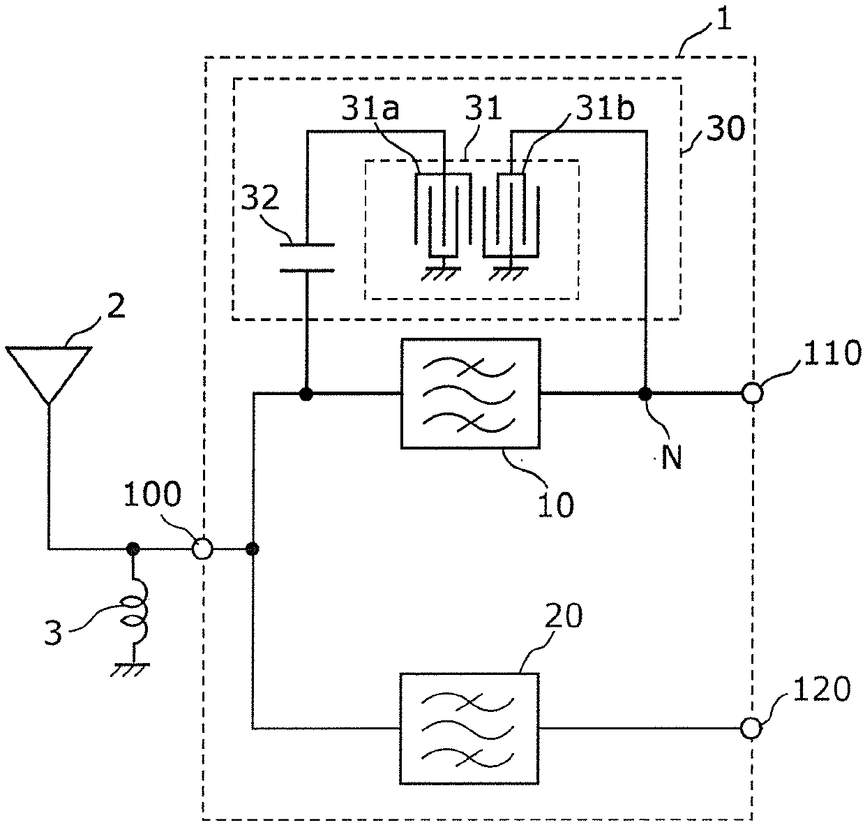
[0051] figure 1 It is a circuit configuration diagram of the multiplexer 1 and its peripheral circuits according to the embodiment. exist figure 1 A multiplexer 1 , an antenna element 2 , and a matching inductor 3 according to the present embodiment are shown.

[0052] The multiplexer 1 includes a transmission filter 10 , a reception filter 20 , a cancel circuit 30 , a common terminal 100 , a transmission terminal (first terminal) 110 , and a reception terminal (second terminal) 120 . The transmission-side filter 10 and the reception-side filter 20 are commonly connected to a common terminal 100 . With this configuration, the multiplexer 1 functions as a duplexer that outputs the high-frequency signal received by the antenna element 2 from the receiving-side terminal 120 via the common terminal 100 and the receiving-side filter 20 The side filter 10 and the common terminal 100 output the high frequency signal input fro...


PUM


Abstract

The present invention provides multiplexers that improve attenuation characteristics of a first filter circuit, and improve the bandpass characteristics of a second filter circuit connected to the first filter circuit. A multiplexer 1 includes a transmission filter 10 and a reception filter 20 that are connected to a common terminal 100, and a cancellation circuit 30 that is connected to the common terminal 100 and a node N on a transmission path and that offsets a component in a certain frequency band flowing through the transmission filter 10. The cancellation circuit 30 includes a capacitive element 32 connected to the common terminal 100, and a longitudinally-coupled resonator 31 including a first end connected to the capacitive element 32 and a second end connected to the node N withno capacitive element interposed therebetween. An impedance in a reception band when viewing the cancellation circuit 30 from the common terminal side 100 is higher than an impedance in the receptionband when viewing the cancellation circuit 30 from the node side N.

Description

technical field [0001] The present invention relates to a multiplexer including a filter circuit. Background technique [0002] In recent years, mobile phones have been required to support multiple frequency bands and multiple wireless systems with one terminal, that is, so-called multi-band and multi-mode. In order to cope with this, a multiplexer for demultiplexing high-frequency signals having a plurality of wireless carrier frequencies is disposed directly below one antenna. [0003] Figure 8 It is a circuit configuration diagram of a duplexer described in Patent Document 1. Figure 8 The duplexer 600 is shown with a splitter and cancellation circuit 640 . The demultiplexer has a transmission-side filter circuit and a reception-side filter circuit. The cancellation circuit 640 is composed of a longitudinally coupled elastic wave resonator 646 and electrostatic capacitors 642 and 644, and generates cancellation components having opposite phases and the same amplitude f...

Claims


Application Information

Patent Timeline
IPC IPC(8): H03H9/44H03H9/72
CPCH03H9/44H03H9/725H03H9/6476H03H9/6483H03H9/6489H03H9/17H03H9/25H03H9/6406H03H9/6479
Inventor 高田俊明
Owner MURATA MFG CO LTD
Why Eureka
Try Eureka