
Eureka
For R&D, Eureka makes reading and utilizing patents & technical documents easy.
Eureka AIR
Designed for self-driven R&D workflows. Generate viable solutions, solve complex R&D challenges, empower your innovation with AI.

Eureka Materials
Designed for material experts only. Revolutionize your material R&D, from search, analyze, to developing new materials.

TechResearch
Generate reliable direction feasibility study reports for your R&D in just a few steps.

TechSeek
Discover and master advanced knowledge NOW. Basics, ideas, possibilities, all at once.

TechMind
As an expert in R&D Theories, TechMind can generates customized viable solutions instantly.

TechRisk
Analyze your overall solution with one click, know your potential R&D risks in advance.

TechMonitor
Get weekly tech updates, stay abreast of the latest tech innovations and key insights.
Ground anchor pull device
A ground anchor and anchor pull technology, applied in the application, cultivation, agriculture and other directions, can solve the problem of wasting wood and other problems, and achieve the effects of low cost, saving natural resources and simple structure
- Summary
- Abstract
- Description
- Claims
- Application Information
AI Technical Summary
Problems solved by technology
Method used
Image

Examples
Embodiment 1
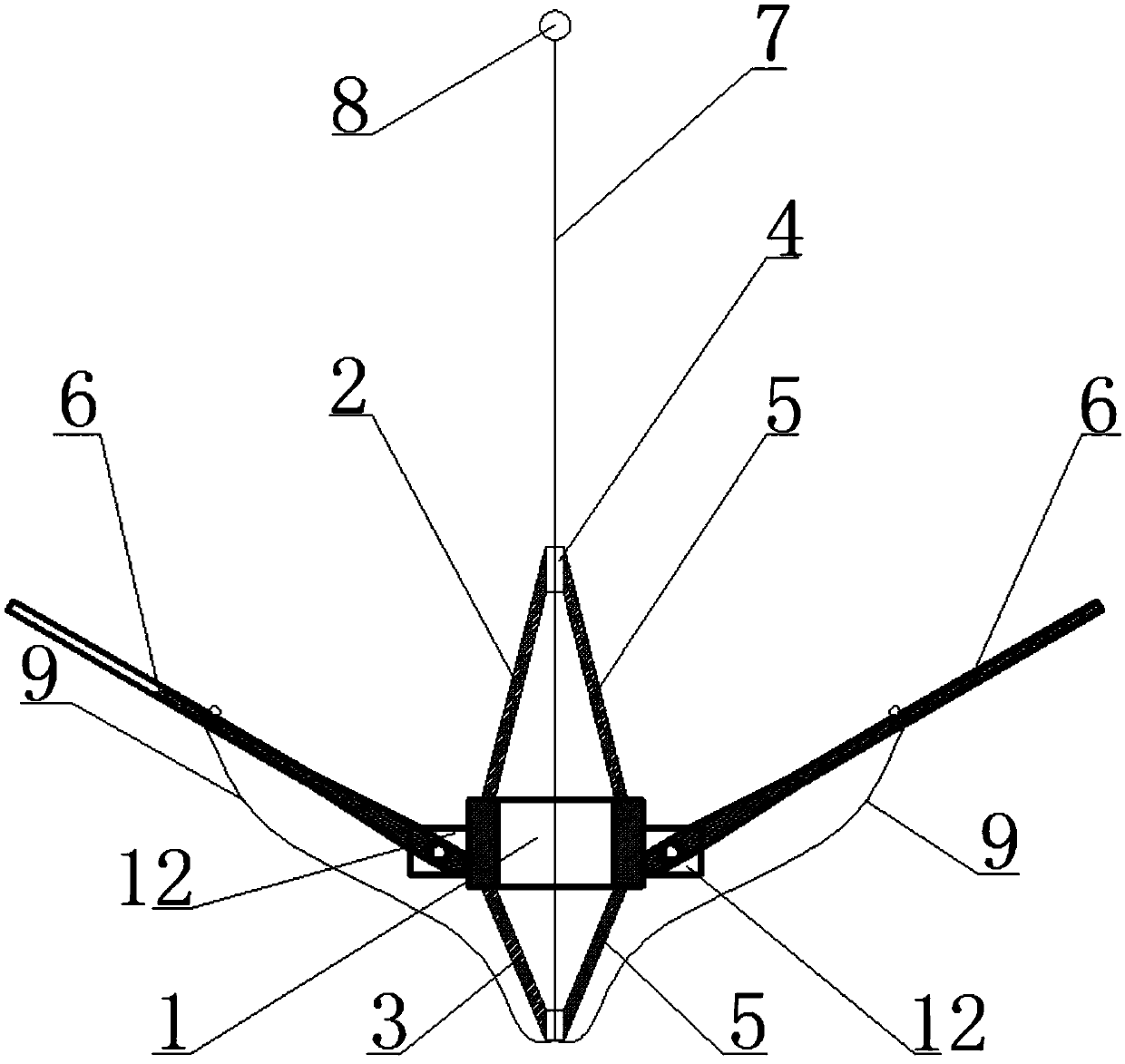
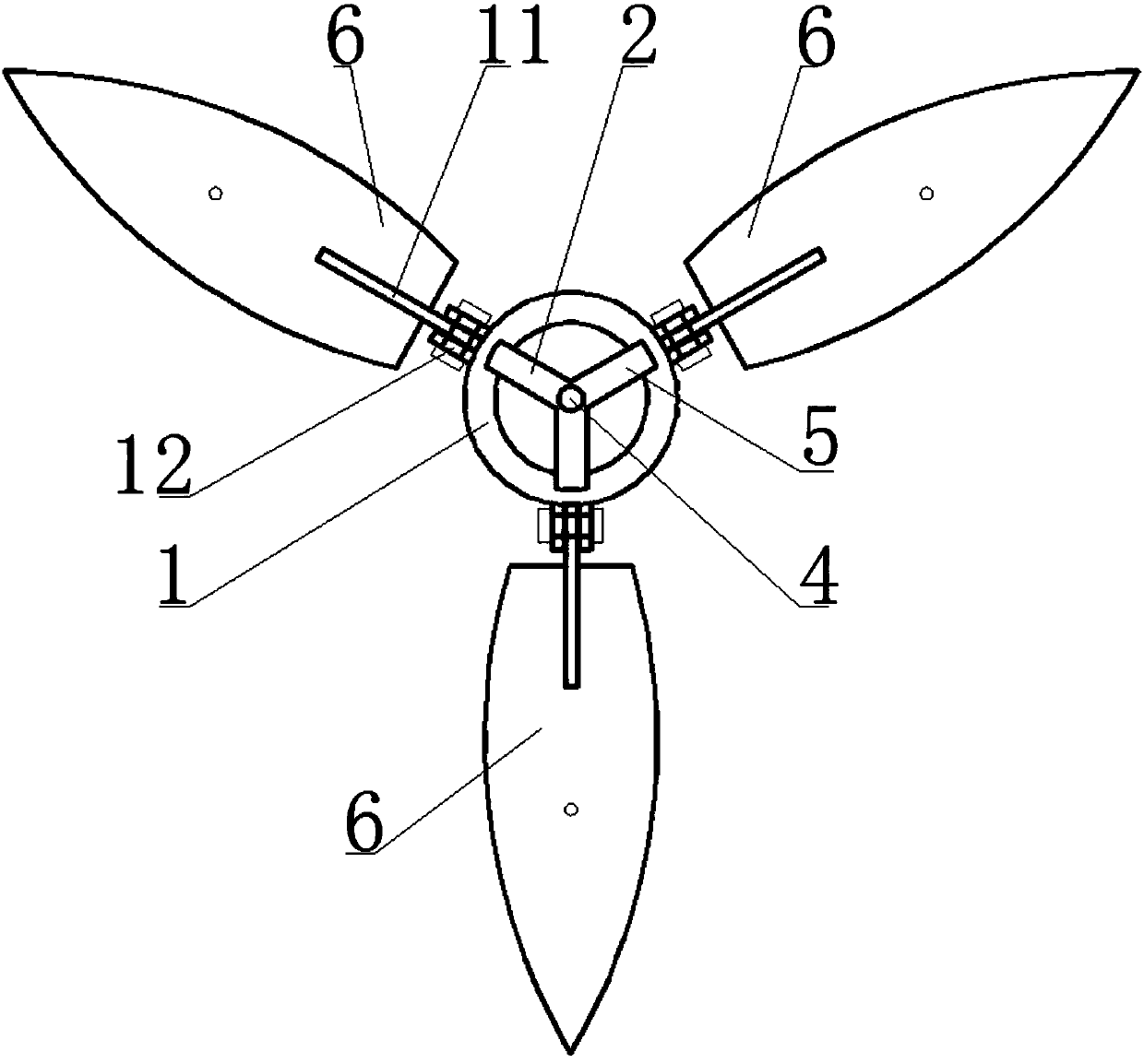
[0036] Such as Figure 1 to Figure 3 As shown, a ground anchor pulling device includes a base 1, a movable component and a pulling component;
[0037] A guiding device can be provided on the base 1; the movable assembly includes two or more movable parts 6 arranged at intervals around the base 1, and the movable part 6 and the base 1 are movably connected by a connecting part 12, and a through hole is provided on the movable part 6 ;The pull assembly includes a pull wire I7 and a pull ring 8. After the pull wire I7 passes through the base 1 and / or the guide device, it is connected with two or more pull wires II9. The number of pull wires II9 corresponds to the number of movable parts 6, and the pull wire II9 passes through The through hole on the movable part 6 is fixed by the fixing part 10, and the top end of the pull wire I7 passes through the pull ring 8.
[0038] The guide device of this embodiment includes a support body I2 and a support body II3 respectively arranged o...
Embodiment 2
[0042] Such as Figure 6 and Figure 7 As shown, the difference between the second embodiment and the first embodiment is that the guiding device includes a conduit 13 passing through the base 1 , and the pull wire I7 passes through the conduit 13 .
Embodiment 3
[0044] Such as Figure 8 and Figure 9 As shown, the difference between the third embodiment and the first embodiment is that there is no guiding device on the base 1, and a hole is drilled on the upper part of the base to fix the pull wire I7. At the bottom, utilize the outer diameter of the steel pipe to push down and stretch the movable part, and then pull the stay wire I7 to make the movable part go deep into the soil to bear the pulling force of the sapling.
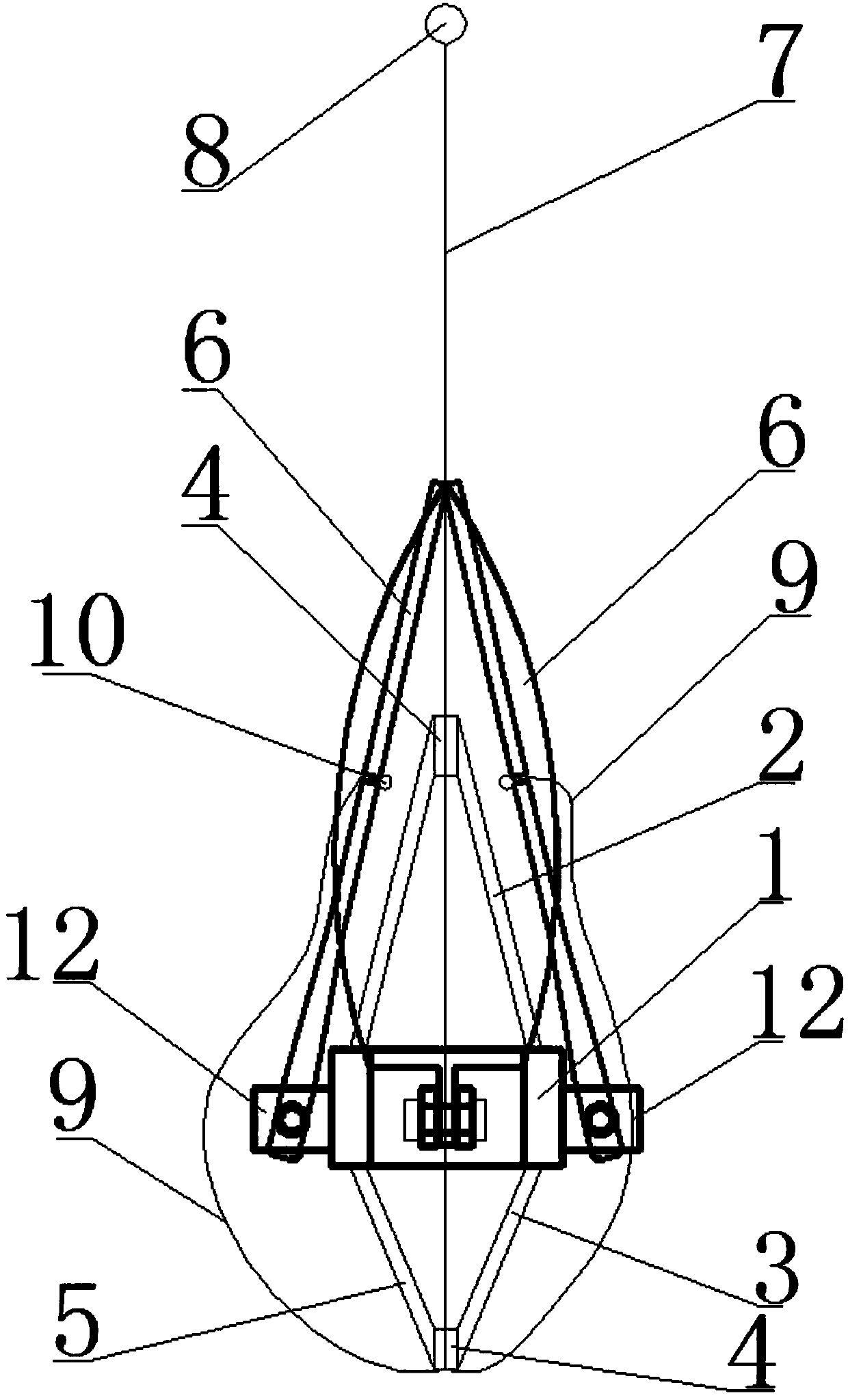
[0045] The use process of embodiment one and embodiment two of the present invention is as follows:
[0046] Such as Figure 4 and Figure 5 As shown, first use a special impact drill to drill a circular hole with a diameter of 6 cm and a depth greater than 60 cm, then send the ground anchor and knot device to the lowest point of the circular hole with a steel pipe with a diameter of 2.5 cm, and then Pull the stay wire Ⅰ to make the movable parts open and plunge into the soil. The maximum expansion angle of the ...
PUM
| Property | Measurement | Unit |
|---|---|---|
| Diameter | aaaaa | aaaaa |
Abstract
Description
Claims
Application Information
 - R&D Engineer
- R&D Manager
- IP Professional
- Industry Leading Data Capabilities
- Powerful AI technology
- Patent DNA Extraction
Browse by: Latest US Patents, China's latest patents, Technical Efficacy Thesaurus, Application Domain, Technology Topic, Popular Technical Reports.
© 2024 PatSnap. All rights reserved.Legal|Privacy policy|Modern Slavery Act Transparency Statement|Sitemap|About US| Contact US: help@patsnap.com