Ultrasonic pipe end machining device

A processing device and ultrasonic technology, applied in the field of metal pipe processing, can solve the problems of low processing efficiency, high scrap rate, fast tool wear, etc., and achieve the effects of high processing accuracy, high yield and long service life

Inactive Publication Date: 2018-05-15
XINXIANG UNIV
View PDF5 Cites 1 Cited by
  • Summary
  • Abstract
  • Description
  • Claims
  • Application Information

AI Technical Summary

Problems solved by technology

[0002] In existing industrial or civil applications, metal pipes, especially copper pipes and aluminum pipes, need to be connected with other components such as pipe joints or pipe sockets during the application process. In order to achieve better sealing or firm connection, often It is necessary to process the nozzle end of the metal pipe, expand it into a bell mouth or other shapes, or shrink it; the existing pipe end processing methods often use single-station and multi-station pipe end processing devices, of which the single-station The station pipe end processing device can process copper and aluminum pipes at one time, but it has fast tool wear, high scrap rate, and is prone to defects such as eccentricity, cracking and drumming; the existing multi-station pipe end processing machines mainly use The multi-station punch performs multiple processing and forming on the pipe end, which effectively solves the problem of high scrap rate. However, because this type of device requires multiple punching and expansion of a single pipe end before it can be formed, there are low processing efficiency and serious mold wear. question

Method used


Image

  • Ultrasonic pipe end machining device
  • Ultrasonic pipe end machining device

Examples


Embodiment Construction

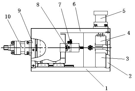
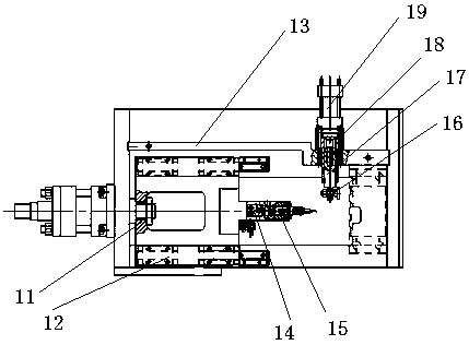
[0010] In order to further illustrate the technical solution of the present invention, the specific implementation manner of the present invention is now described in conjunction with the accompanying drawings, as figure 1 , figure 2 , in this example, steel plates are selected to make it into the bottom plate 1, and the bottom plate 1 is installed on the lower ends of the left side plate 9 and the right side plate 2, and the two ends of the bottom plate 1 are respectively connected with the lower ends of the left side plate 9 and the right side plate 2 Select steel plate as the material of right side plate 2, it is installed on the right end of base plate 1 and top plate 6 and is connected with the right end of base plate 1 and top plate 6 respectively, offers feed inlet on the right side plate 2 simultaneously, can make to be processed The pipe enters between the lower clamping die 3 and the upper clamping die 4 from the feed port; the lower clamping die processed by the en...


PUM


Abstract

An ultrasonic pipe end machining device is characterized by comprising a die clamping mechanism, a pipe end positioning mechanism, a transverse ultrasonic flaring mechanism, a top plate, a bottom plate, a front plate, a left plate and a right plate. The die clamping mechanism is arranged between the top plate and the bottom plate, and the pipe end positioning mechanism is installed on the front plate and fixedly connected with the front plate; the transverse ultrasonic flaring mechanism is installed on the left plate; the top plate is arranged between the left plate and the right plate and islocated at the upper ends of the left and right plates; the bottom plate is arranged between the left and right plates and located on the left plate; the front plate is arranged between the top plateand the bottom plate; the left plate is arranged at the left end of the top plate and the left end of the bottom plate and connected with the top plate and the bottom plate; the right plate is arranged between the top plate and the bottom plate and connected with the right ends of the top plate and the right end of the bottom plate. The device has the advantages that the efficiency is high and a die is durable.

Description

technical field [0001] The invention belongs to the field of metal tube processing, and in particular relates to a processing device for processing the nozzles of copper tubes and aluminum tubes by shrinking, expanding or ring-shaped convex-concave processing. Background technique [0002] In existing industrial or civil applications, metal pipes, especially copper pipes and aluminum pipes, need to be connected with other components such as pipe joints or pipe sockets during the application process. In order to achieve better sealing or firm connection, often It is necessary to process the nozzle end of the metal pipe, expand it into a bell mouth or other shapes, or shrink it; the existing pipe end processing methods often use single-station and multi-station pipe end processing devices, of which the single-station The station pipe end processing device can process copper and aluminum pipes at one time, but it has fast tool wear, high scrap rate, and is prone to defects such...

Claims


Application Information

Patent Timeline
Patent Type & Authority Applications(China)
IPC IPC(8): B21D41/00B21D43/02
CPCB21D41/00B21D43/02
Inventor 唐军李文星肖淼鑫
Owner XINXIANG UNIV
Why Eureka
Try Eureka