Third axis group mechanism matched with positive axis of movable machine

A technology of centering machine and shaft group, which is applied in the direction of metal processing machinery parts, large fixed members, clamping, etc. It can solve the problems that complex parts cannot be realized, and achieve the effect of convenient installation and improved motion accuracy

Inactive Publication Date: 2015-09-09
NANJING JIANKE MACHINERY
View PDF7 Cites 0 Cited by
  • Summary
  • Abstract
  • Description
  • Claims
  • Application Information

AI Technical Summary

Problems solved by technology

[0005] The technical problem solved by the invention is the problem that the existing rotary milling machine tool cannot realize the one-time processing and forming of complex parts, and the efficiency is not high

Method used


Image

  • Third axis group mechanism matched with positive axis of movable machine
  • Third axis group mechanism matched with positive axis of movable machine
  • Third axis group mechanism matched with positive axis of movable machine

Examples


Embodiment 1

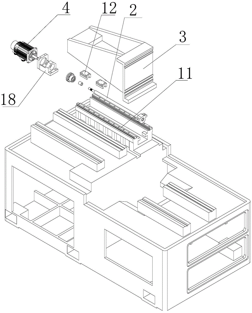
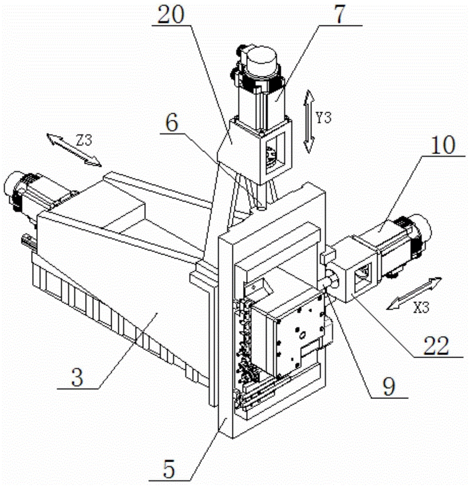
[0047] see Figure 1 to Figure 3 , The third shaft group mechanism of the present invention is composed of three major parts: Z3 shaft group, Y3 shaft group, and X3 shaft group.

[0048] The Z3-axis group includes a Z3-axis rail 11, a Z3-axis slider 12, a Z3-axis seat, a Z3-axis slide plate 3, a Z3-axis motor 4, a Z3-axis motor seat 18, and a Z3-axis coupling 17. The Z3 axis rail 11 is installed on the machine bed, and the Z3 axis slide block 12 matched with the Z3 axis rail 11 is installed on the bottom of the Z3 axis slide plate 3 . The Z3 axis slide plate 3 is slidably installed on the machine tool through the sliding pair formed by the Z3 axis rail 11 and the Z3 axis slide block 12 . On the bed that Z3 shaft seat is fixed, bearing is housed in it, Z3 shaft nut is installed at the bottom of Z3 shaft slide plate 3, Z3 shaft motor seat 18 is fixed on the bed, is used for installing Z3 shaft motor 4, and Z3 shaft bearing is housed in it. Z3 shaft screw mandrel 2 passes Z3 sh...

Embodiment 2

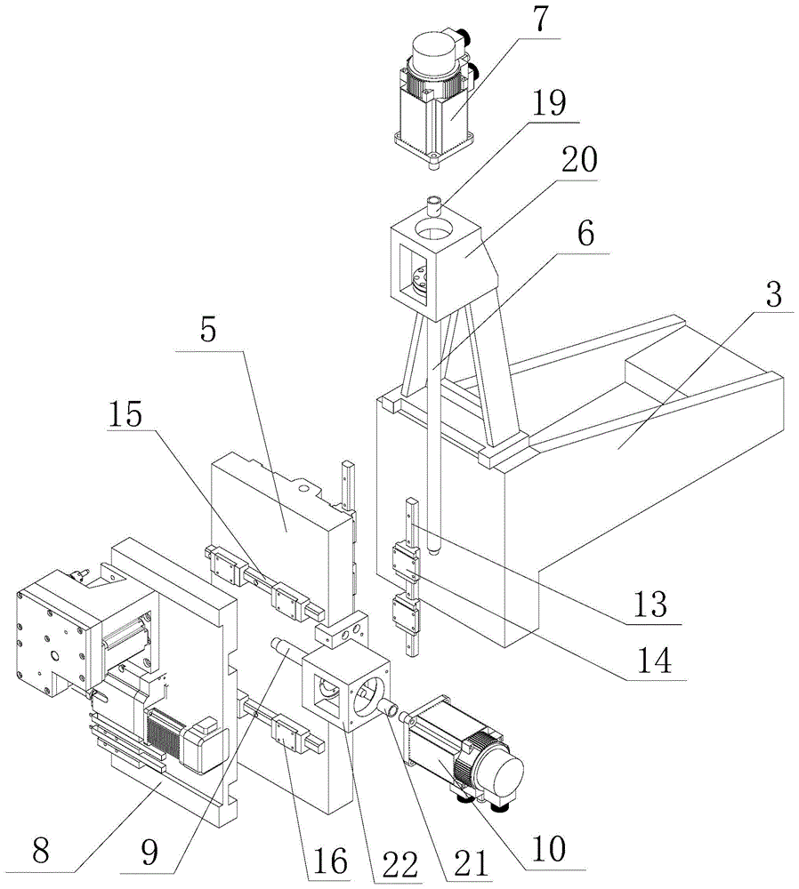
[0057] The difference between this embodiment and Embodiment 1 is that the tool mounting seat 8 is a turret, and the X3-axis slider 16 matched with the X3 axis rail 15 is installed on the turret, and the tool is installed on the turret, and the 360° of the turret can be used. Rotation to achieve tool change, the rest of the structure of this embodiment is the same as that of Embodiment 1, see Embodiment 1 for details, and will not be described in detail here. At this time, the turret rotates 360°, and the tools at each station of the turret can be changed flexibly to realize the processing of the workpiece. This assembly structure not only saves space, but also can be installed on the turret. Increase the variety and quantity of cutting tools, power heads, etc. to a certain extent, and the disc design is conducive to chip removal when the tool is processing parts, and to a greater extent strengthens the rigidity of the tool when processing parts. Such a structure increases the...

Embodiment 3

[0059] The difference between this embodiment and Embodiment 1 is that the tool mounting seat 8 is composed of a turret and an X3-axis slide plate, the turret is installed on the X3-axis slide plate, and the X3-axis slide block 16 matched with the X3 axis rail 15 is installed on the X3-axis slide plate Above, the tool is installed on the turret, and the tool can be changed by using the 360-degree rotation of the turret. The rest of the structure of this embodiment is the same as that of Embodiment 1, see Embodiment 1 for details, and will not be described in detail here. At this time, the turret rotates 360°, and the tools at each station of the turret can be changed flexibly to realize the processing of the workpiece. This assembly structure not only saves space, but also can be installed on the turret. Increase the variety and quantity of cutting tools, power heads, etc. to a certain extent, and the disc design is conducive to chip removal when the tool is processing parts, a...


PUM


Abstract

The invention discloses a third axis group mechanism matched with a positive axis of a movable machine. The third axis group mechanism comprises a Z3 axis group, a Y3 axis group and an X3 axis group, the Z3 axis group comprises a Z3 axis lead screw, a Z3 axis sliding plate and a Z3 axis servo motor, the Y3 axis group comprises a Y3 axis sliding plate, a Y3 axis lead screw and a Y3 axis servo motor, and the X3 axis group comprises a tool mounting seat, an X3 axis lead screw and an X3 axis servo motor. The third axis group mechanism has the advantages that the third axis group mechanism matched with the positive axis of the movable machine is matched with a positive axis structure of a numerical control movable turning-milling machine tool, and the numerical control movable turning-milling machine tool with a positive six-axis structure can be formed to avoid unnecessary time waste due to the fact that tool structures are arranged on the same X axis sliding plate, tool arrays are mutually connected, and independent operation cannot be realized. When the tool arrays on the positive axis structure of the machine tool are used for machining workpieces, an independent tool array on the third axis group can simultaneously machine the workpieces in different working procedures.

Description

technical field [0001] The invention relates to a third shaft group mechanism cooperating with the positive shaft of a centering machine. Background technique [0002] In the existing centering machine market, there has been research on the technology of machine tool motion axes, and the most widely used one is the three-axis axis group consisting of X1 axis group, Y1 axis group, and Z1 axis group. Axis center turning and milling machine; or, when the sub-axis structure is added with Z2 axis group, it can be combined with the positive axis structure to form a four-axis center turning and milling machine; or, when the sub-axis is composed of X2 axis group and Z2 axis group The composed sub-axis structure cooperates with the positive axis structure to form a five-axis center turning and milling machine tool; or, when the sub-axis structure composed of X2 axis group, Z2 axis group, and Y2 axis group cooperates with the positive axis structure to form a six-axis centering machin...

Claims


Application Information

Patent Timeline
Patent Type & Authority Applications(China)
IPC IPC(8): B23Q1/46B23Q5/40B23P23/02B23Q5/36B23Q3/155
CPCB23P23/02B23Q1/46B23Q1/626B23Q3/15506B23Q5/28B23Q5/36B23Q5/40B23Q5/44B23Q2705/16
Inventor 王建飞
Owner NANJING JIANKE MACHINERY
Why Eureka
Try Eureka