Laser scanning device and method for making three-dimensional object

A laser scanning device, a technology for three-dimensional objects, applied in optics, optical components, instruments, etc., can solve the problems of slowing down the forming speed of three-dimensional objects, affecting the forming accuracy of three-dimensional objects, and difficult to achieve high precision and high forming speed. The effect of increasing the molding speed

Inactive Publication Date: 2014-11-12
HUNAN FARSOON HIGH TECH CO LTD
View PDF5 Cites 18 Cited by
  • Summary
  • Abstract
  • Description
  • Claims
  • Application Information

AI Technical Summary

Problems solved by technology

In the existing method for manufacturing three-dimensional objects, the laser scanning step generally uses a single spot of the same size to scan. This laser scanning method can realize the manufacture of three-dimensional objects, but the accuracy of the three-dimensional object is improved due to the use of smaller-sized spots for scanning. At the same time, the forming speed of the three-dimensional object is slowed down; and if a larger-sized light spot is used for scanning, the forming speed of the three-dimensional object is improved, and the forming accuracy of the three-dimensional object may be affected at the same time. Therefore, the single light spot of the prior art It is difficult to achieve the effect of high precision and high molding speed by scanning method to manufacture three-dimensional objects

Method used


Image

  • Laser scanning device and method for making three-dimensional object
  • Laser scanning device and method for making three-dimensional object
  • Laser scanning device and method for making three-dimensional object

Examples


Embodiment approach 1

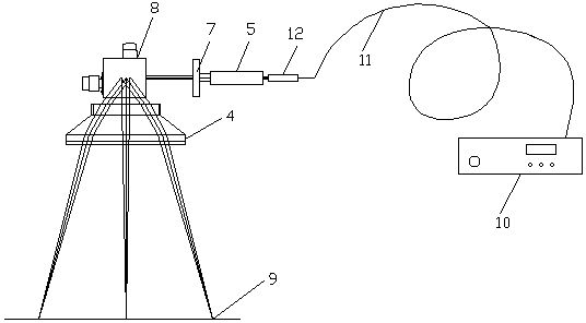
[0037]Embodiment 1: The beam adjustment system includes a fixed magnification beam expander, an F-Theta lens, and a diaphragm, and the laser, a fixed magnification beam expander, a galvanometer system, and an F-Theta lens form a first optical path unit, and the F -Theta lens is used to form a focused spot of uniform size on the working plane by the laser beam reflected by the galvanometer system. The fixed magnification beam expander is arranged between the laser and the galvanometer system. The aperture, so that the aperture is set between the fixed magnification beam expander and the vibrating mirror system, when scanning the filling area, the aperture is lowered, so that the aperture does not appear in the first optical path unit.

Embodiment approach 2

[0038] Embodiment 2: The beam adjustment system includes a dynamic focusing module and a diaphragm, the dynamic focusing module includes a dynamic diverging mirror and a focusing mirror, and the laser, the dynamic diverging mirror, the focusing mirror and the vibrating mirror system form a second optical path unit, and the The above-mentioned dynamic diverging mirror and focusing mirror are sequentially arranged between the laser and the galvanometer system. When scanning the contour area, the diaphragm is raised so that the diaphragm is arranged between the dynamic diverging mirror and the focusing mirror. stop, so that the stop does not appear in the second optical path unit.

[0039] The apertures in Embodiment 1 and Embodiment 2 can be raised and lowered by motor control. When the aperture rises, that is, the aperture appears in the first optical path unit and / or the second optical path unit, which is equivalent to starting the filter function. When the diaphragm drops, it...

Embodiment approach 3

[0040] Embodiment 3: The beam adjustment system includes a variable magnification beam expander and an F-Theta lens, the variable magnification beam expander is arranged between the laser and the galvanometer system, and the F-Theta lens is used to The laser beam reflected by the vibrating mirror system forms a focused spot of uniform size on the working plane, and the first spot and the second spot are respectively obtained by adjusting the magnification of the variable magnification beam expander.

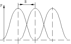
[0041] Preferably, in order to further improve the accuracy and molding speed of the three-dimensional object, the first light spot and the second light spot should satisfy the formula: d 2 ≤2d 1 , where d 1 is the first spot size, d 2 is the second spot size.

[0042] In specific implementation, the laser is CO 2 A laser or a fiber laser, and of course other types of lasers can also be used.

[0043] In the laser scanning device for manufacturing three-dimensional objects o...


PUM


Abstract

The invention provides a laser scanning device and method for making a three-dimensional object. The laser scanning device comprises a laser device, a galvanometer system, a control system and a beam adjustment system. The control system divides spots to be scanned on each section of a workpiece into an outline region and a filling region; when the outline region is scanned, the control system controls the laser device through the galvanometer system and controls the beam adjustment system at the same time to select first light spots with a smaller size for scanning; when the filling region is scanned, the control system controls the laser device through the galvanometer system and controls the beam adjustment system at the same time to select second light spots with a larger size for scanning. According to the laser scanning device and method for making the three-dimensional object, by the adoption of a regional scanning mode, the forming speed of the three-dimensional object is increased on the premise of guaranteeing the accuracy of the made three-dimensional object.

Description

technical field [0001] The invention belongs to the field of three-dimensional object manufacturing, and in particular relates to a laser scanning device and method for manufacturing three-dimensional objects. Background technique [0002] The manufacturing method of the three-dimensional object mainly includes the process steps of layered slicing, powder feeding and laser scanning, wherein laser scanning is a key factor affecting the accuracy and molding speed of the three-dimensional object. In the existing manufacturing methods of three-dimensional objects, the laser scanning step generally uses a single spot of the same size to scan. This laser scanning method can realize the manufacture of three-dimensional objects, but the accuracy of the three-dimensional object is improved due to the use of smaller-sized spots for scanning. At the same time, the forming speed of the three-dimensional object is slowed down; and if a larger-sized light spot is used for scanning, the fo...

Claims


Application Information

Patent Timeline
Patent Type & Authority Applications(China)
IPC IPC(8): G02B26/10
Inventor 鲍光许小曙
Owner HUNAN FARSOON HIGH TECH CO LTD
Why Eureka
Try Eureka