Cutting tool

A technology of cutting tools and cutting blades, which is applied in the direction of cutting tools for lathes, turning equipment, manufacturing tools, etc., can solve the problems that affect the market competitiveness of manufacturers, low cutting precision, and poor user experience, and achieve the purpose of strengthening the market Competitiveness, high precision, good performance results

Pending Publication Date: 2018-05-15
张伟东
View PDF10 Cites 3 Cited by
  • Summary
  • Abstract
  • Description
  • Claims
  • Application Information

AI Technical Summary

Problems solved by technology

[0002] At present, the tool holder on the traditional cutting tool, when the user pulls the pulley, the cutting blade is likely to vibrate on the tool holder and shift laterally, resulting in low cutting accuracy and poor user experience, which affects the manufacturer's Market Competitiveness

Method used


Image

  • Cutting tool
  • Cutting tool
  • Cutting tool

Examples


Embodiment Construction

[0021] It should be noted that all directional indications (such as up, down, left, right, front, back...) in the embodiments of the present invention are only used to explain the relative relationship between the components in a certain posture (as shown in the accompanying drawings). When the positional relationship, movement conditions, etc., if the specific posture changes, the directional indication will also change accordingly. In addition, the technical solutions of the various embodiments can be combined with each other, but it must be based on the realization of those skilled in the art. When the combination of technical solutions is contradictory or cannot be realized, it should be considered that the combination of technical solutions does not exist , nor within the scope of protection required by the present invention.

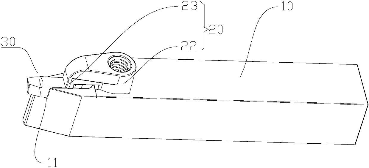
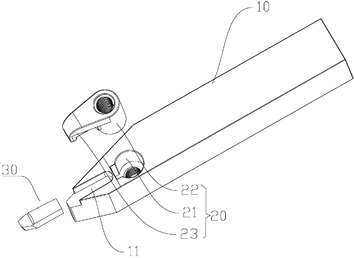
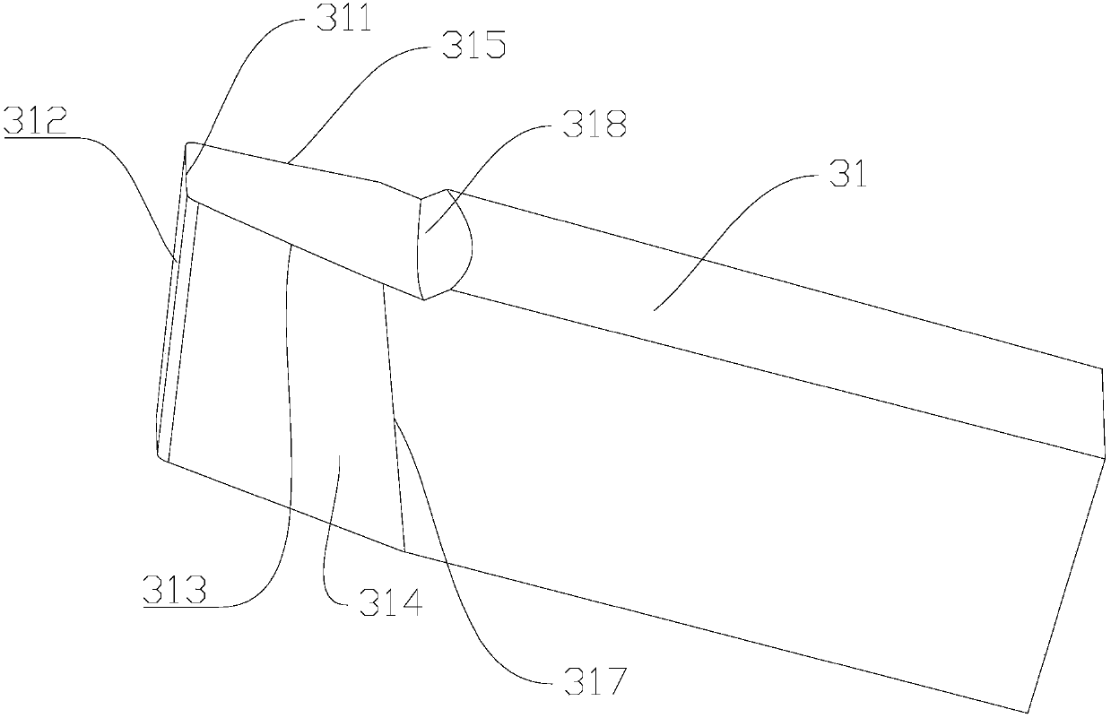
[0022] refer to figure 1 , figure 2 , image 3 , Figure 4 , the present invention is a cutting tool, including a tool holder 10, a fastening...


PUM


Abstract

The invention discloses a cutting tool, and relates to the field of machinery manufacturing metal cutting machining. The cutting tool comprises a tool holder. Cutting faces with three cutting edges are formed at an end of the tool holder by means of grinding, and a chip removal groove is further formed in a joint of the cutting faces and the tool holder. The cutting tool has the advantages that the cutting faces with the three cutting edges are formed in the end of the tool holder by means of grinding, the three cutting edges can simultaneously vertically and horizontally transversely move when belt pulleys are about to be lathed by users, accordingly, the belt pulleys can be lathed, and the cutting tool is high in efficiency; the chip removal groove is formed in the cutting tool, and accordingly chips can be smoothly removed; accumulated chips are difficult to stick to the cutting tool, built-up edges can be prevented, heat can be quickly dissipated, abrasion and tipping can be prevented, and accordingly the service life of the cutting tool can be prolonged.

Description

technical field [0001] The invention relates to the field of mechanical manufacturing metal cutting processing, in particular to a cutting tool. Background technique [0002] At present, the tool holder on the traditional cutting tool, when the user pulls the pulley, the cutting blade is likely to vibrate on the tool holder and shift laterally, resulting in low cutting accuracy and poor user experience, which affects the manufacturer's Market Competitiveness. Contents of the invention [0003] Therefore, in order to solve the above problems, the present invention provides a cutting tool with stable structure, good performance and high precision. [0004] The technical solution adopted by the present invention to solve its technical problems is: [0005] A cutting tool, including a tool holder, the tool holder is provided with a mounting groove for placing a cutting blade; [0006] A fastening assembly, the fastening assembly is arranged on the tool holder, and is used f...

Claims


Application Information

Patent Timeline
Patent Type & Authority Applications(China)
IPC IPC(8): B23B27/16
CPCB23B27/1662
Inventor 张伟东
Owner 张伟东
Why Eureka
Try Eureka