Anti-cavitation laser cladding construction method for water pump turbines suitable for power station sites

A water pump turbine, laser cladding technology, applied in the direction of metal material coating process, coating, etc., to achieve the effect of expanding application, small size, and easy on-site construction

Active Publication Date: 2020-02-18
XIAN UNIV OF TECH
View PDF6 Cites 0 Cited by
  • Summary
  • Abstract
  • Description
  • Claims
  • Application Information

AI Technical Summary

Problems solved by technology

[0007] The purpose of the present invention is to provide a pump-turbine anti-cavitation laser cladding construction method suitable for the power station site, which solves the problem that the existing cladding technology cannot carry out long-term continuous cladding of complex surfaces under complex site conditions

Method used


Image

  • Anti-cavitation laser cladding construction method for water pump turbines suitable for power station sites
  • Anti-cavitation laser cladding construction method for water pump turbines suitable for power station sites
  • Anti-cavitation laser cladding construction method for water pump turbines suitable for power station sites

Examples


Embodiment 1

[0057] Embodiment 1 cladding Ni60+WC composite coating on martensitic stainless steel

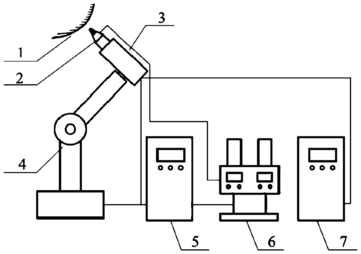
[0058] 1) Preliminary preparation: see figure 1 Install and debug the cladding system.

[0059] In this example, the substrate sample is 12mm thick wire-cut to a size of 100×60mm, ultrasonically cleaned with absolute ethanol for 10 minutes, sand blasted and then ultrasonically cleaned with acetone for 10 minutes before use. In this example, the cladding surface is at the 100° orientation in the vertical plane, the horizontal direction is 0°, and the counterclockwise direction is the positive direction. A programmable robot is used to align the laser and the powder feeding head on the cladding surface. Cause damage, the laser and the powder feeding head are in the 70° orientation, adjust the distance between the powder feeder and the substrate to ensure that the laser defocus is positive defocus 13mm. Choose laser power 700W, cladding speed 250mm / min, overlap rate 40%, and cladding area 80...

Embodiment 2

[0062] Embodiment 2 Cladding Ni60 coating on martensitic stainless steel

[0063] 1) Preliminary preparation: see figure 1 Install and debug the cladding system. In this example, the substrate sample is 12mm thick wire-cut to a size of 100×60mm, ultrasonically cleaned with absolute ethanol for 10 minutes, sand blasted and then ultrasonically cleaned with acetone for 10 minutes before use. In this example, the cladding surface is at the 100° orientation in the vertical plane, the horizontal direction is 0°, and the counterclockwise direction is the positive direction. Use the robot to align the laser and the powder feeding head on the cladding surface, in order to prevent the laser reflection from causing damage to the laser , the laser and the powder feeding head are in a 70° orientation, and the distance between the laser and the substrate is adjusted to ensure that the laser defocus is positive defocus of 13mm. Choose laser power 700W, cladding speed 250mm / min, overlap rat...

Embodiment 3

[0065] Example 3 Cladding Ni60+WC Composite Coating on Martensitic Stainless Steel

[0066] 1) Preliminary preparation: see figure 1 Install and debug the cladding system. In this example, the substrate sample is 12mm thick wire-cut to a size of 100×60mm, ultrasonically cleaned with absolute ethanol for 10 minutes, sand blasted and then ultrasonically cleaned with acetone for 10 minutes before use. In this example, the cladding surface is at the 100° orientation in the vertical plane, the horizontal direction is 0°, and the counterclockwise direction is the positive direction. Use the robot to align the laser and the powder feeding head on the cladding surface, in order to prevent the laser reflection from causing damage to the laser , the laser and the powder feeding head are in a 70° orientation, and the distance between the laser and the substrate is adjusted to ensure that the laser defocus is positive defocus of 13mm. Choose laser power 700W, cladding speed 250mm / min, o...


PUM

PropertyMeasurementUnit
particle diameteraaaaaaaaaa

Abstract

The invention discloses an anti-cavitation-erosion laser cladding construction method suitable for a pump turbine of a power station site. The anti-cavitation-erosion laser cladding construction method is conducted specifically according to the following steps that first, checking and recording before repairing are conducted, the blade surface of a pump water wheel is cleaned, and a laser claddingarea is identified; second, the laser cladding area on a blade of the pump water wheel is subjected to grinding, repairing welding, finish welding, finish repairing and the like, and the blade surface is subjected to activation treatment; third, a cladding system is mounted and debugged; and fourth, cladding is conducted. The cladding system and a specially-designed powder feeding nozzle are utilized, large-area continuous laser cladding can be conducted on the plane or the complex curved surface of any spatial orientation where a robot mechanical arm can reach, and thus a coating uniform inthickness and organization structure and free of obvious defects such as pores and cracks can be obtained.

Description

technical field [0001] The invention belongs to the technical field of hydropower equipment, and in particular relates to a cavitation-resistant laser cladding construction method for water pumps and turbines suitable for power station sites. Background technique [0002] Many high-head pumped-storage power station pump turbines in my country have a large range of operating head, that is, a large change in head and a large flow rate. When the water flows through the runner blades, the flow rate is high. The operating conditions of the unit are complex and changeable, and cavitation is more likely to occur than conventional turbines. , the water outlet edge of the runner blades of the pump turbines of many pumped storage power stations in China has cavitation to varying degrees. The cavitation of the pump turbine seriously affects the efficiency, service life, maintenance cycle and maintenance workload of the pump turbine. The strong vibration and noise caused by cavitation wi...

Claims


Application Information

Patent Timeline
Patent Type & Authority Patents(China)
IPC IPC(8): C23C24/10B23P6/00
CPCB23P6/007C23C24/103
Inventor 赵道利黄秋红杨宛利孙维鹏南海鹏罗兴锜梁武科马薇
Owner XIAN UNIV OF TECH
Why Eureka
Try Eureka