Filling pile construction scheme and funnel thereof

A technology of cast-in-situ piles and funnels, which is applied to sheet pile walls, foundation structure engineering, construction, etc., can solve problems such as troubles, and achieve the effect of convenient and quick operation

Active Publication Date: 2018-05-15
广东中南建设有限公司
View PDF5 Cites 3 Cited by
  • Summary
  • Abstract
  • Description
  • Claims
  • Application Information

AI Technical Summary

Problems solved by technology

[0002] Cast-in-situ piles are made by directly opening holes on the designed pile positions with a circular cross-section. After the holes are formed, a reinforcement cage is placed in the holes and concrete is poured. The commonly used method is drilling and pouring. The specific process includes: Site leveling→pile position setting out→excavation of slurry pool and slurry trench→casing burial→drilling rig in place, hole position correction→hole forming, mud circulation, removal of waste slurry and sludge→first hole cleaning→quality acceptance→ Lower the reinforcement cage and steel conduit → clear the hole for the second time → pour underwater concrete → form a pile. During the pouring of concrete, connect a funnel to the steel conduit, pour the concrete into the funnel, and pour the concrete into the underwater pouring concrete for the first time It is the most important step. This step is directly related to the quality of the whole pile. Generally, a rubber ball or concrete ball suitable for its outlet is hoisted in the funnel in advance, and the hanging rope is cut after the concrete in the funnel reaches the predetermined amount. Make the ball or concrete ball and the concrete leak together, which effectively avoids the segregation of the concrete by the mud erosion, but it needs to be cut manually every time, which is troublesome

Method used


Image

  • Filling pile construction scheme and funnel thereof
  • Filling pile construction scheme and funnel thereof
  • Filling pile construction scheme and funnel thereof

Examples


Embodiment 1

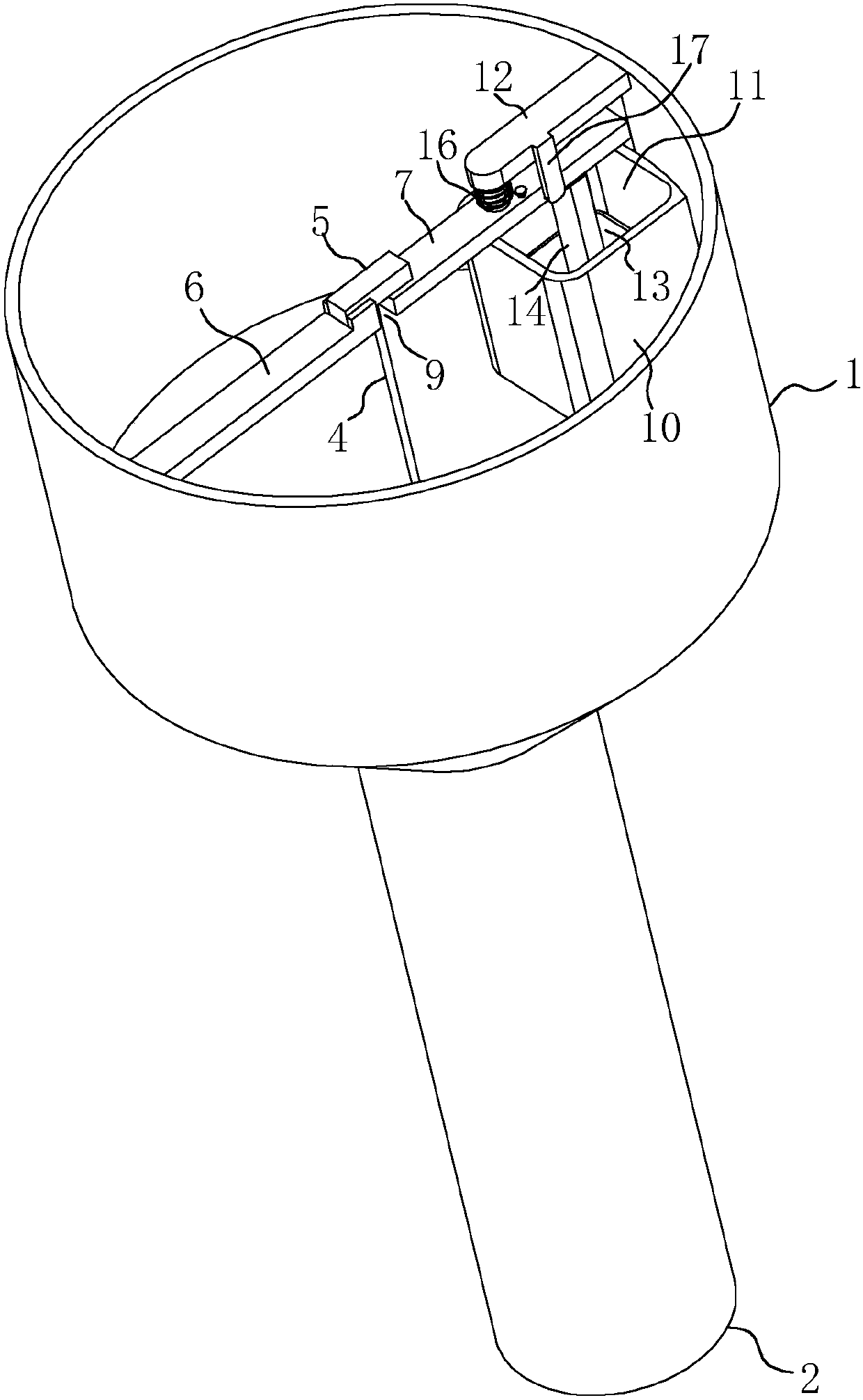
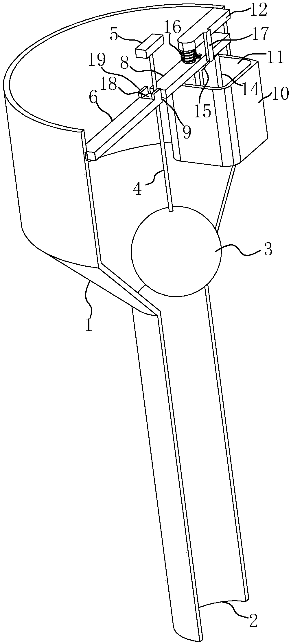
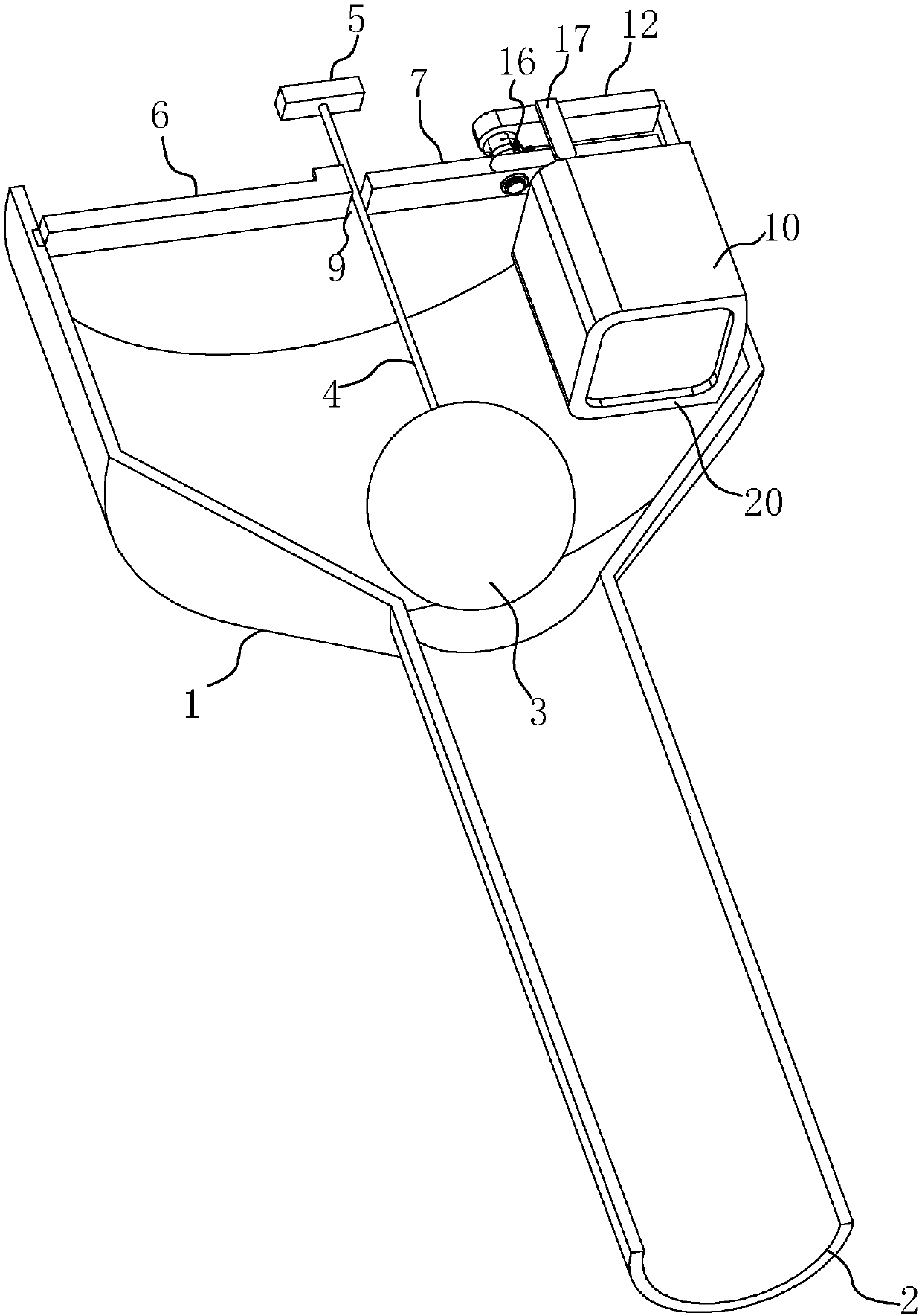
[0040] Embodiment 1: the funnel that is used for cast-in-situ pile construction, as figure 1 and figure 2 As shown, a bucket body 1 is included, an outlet 2 is arranged at the bottom of the bucket body 1, and a cross bar is arranged radially on the top of the bucket body 1, and a ball 3 adapted to the outlet 2 is hoisted on the cross bar, and the ball 3 A suspension rope 4 is fixed on the top, and a block body 5 is fixed on the top of the suspension rope 4, wherein the crossbar includes a fixed rod 6 and a movable rod. The middle part of the rotating rod 7 is rotatably connected to the protruding bar 12, there is a gap 9 between the movable rod and the end of the rotating rod 7 for the passage of the hanging rope 4, and the block 5 is placed on the fixed rod 6 and the rotating rod 7 to realize hoisting In this way, the outlet 2 is blocked by means of the ball 3 so that the concrete added to the bucket body 1 will not leak immediately; in addition, a coaming plate 10 is provi...

Embodiment 2

[0044] Embodiment 2: the funnel that is used for cast-in-situ pile construction, as Figure 4 and Figure 5 As shown, the difference between it and Embodiment 1 is that the movable rod is a sliding rod 8, and the sliding rod 8 is horizontally slidably connected to the bucket body 1, and the linkage mechanism therein includes a vertical rod 21 fixed on the floating block 13, and at the same time The bottom of the slide bar 8 is fixed with a projection 22, and the top of the vertical bar 21 is provided with a second wedge-shaped surface 24 that abuts against the projection 22 and drives the slide bar 8 to move away from the fixed bar 6, so that the end of the slide bar 8 part no longer supports the block body 5 to realize the falling and discharging of the block body 5 and the sphere 3, wherein when the block body 5 is placed, the length of the block body 5 on the slide bar 8 is greater than the length on the fixed bar 6, so that The center of gravity of the block body 5 is bia...

Embodiment 3

[0046] Embodiment 3: cast-in-place pile construction scheme, as Figure 6 As shown, the specific process is as follows:

[0047] 1. Measurement and setting out

[0048] Establish a temporary construction control network: In order to ensure the accuracy of pile positioning, it is planned to use the methods of peripheral control network and on-site fixed-point control network for construction measurement and fixed-point;

[0049] ⑴Establish the peripheral control network: select the control axis according to the relationship between the axes of the construction drawings, and extend it to the outside of the construction site to establish a control point network, so that the measurement review can be carried out when the pile position is checked;

[0050] ⑵Establishment of on-site control network: due to the large staggered axes of this project, the off-site control network cannot fully determine the direction and fixed point of the axis, so it is necessary to establish a solid n...


PUM


Abstract

The invention discloses a filling pile construction scheme and a funnel thereof. The filling pile construction scheme is characterized in that an outlet is formed in the bottom of a funnel body, a sphere which is located in the outlet and adapts to the funnel body is lifted in the funnel body, a lifting rope which is fixed to the sphere is arranged on the sphere, a block is fixed to one end, whichis far from the sphere, of the lifting rope, cross rods are arranged on the top of the funnel body, the cross rods include a fixed rod and a movable rod, a gap which is used for the lifting rope to pass through is formed between the ends of the fixed rod and the movable rod, the width of the gap is less than the block, a vertical guide groove is formed in the funnel body, a floating block is arranged in the guide groove, and a linking mechanism which is used for linking one end, which is close to the fixed rod, of the movable rod to move away when the concrete level in the funnel body reachesthe preset height is arranged on the floating block; concrete is continuously added to the funnel body, the concrete level in the funnel body continuously rises, the floating block continuously movesupwards until the level rises to the preset height, and then the end of the movable rod is linked to move away, so that the block falls off; and at the moment, the sphere and concrete are dischargedfrom the outlet together, and the lifting rope does not need to be manually sheared off, so that the operation is convenient.

Description

technical field [0001] The invention relates to the construction field of cast-in-place piles, in particular to a construction scheme of cast-in-place piles and a funnel thereof. Background technique [0002] Cast-in-situ piles are made by directly opening holes on the designed pile positions with a circular cross-section. After the holes are formed, a reinforcement cage is placed in the holes and concrete is poured. The commonly used method is drilling and pouring. The specific process includes: Site leveling→pile position setting out→excavation of slurry pool and slurry trench→casing burial→drilling rig in place, hole position correction→hole forming, mud circulation, removal of waste slurry and sludge→first hole cleaning→quality acceptance→ Lower the reinforcement cage and steel conduit → clear the hole for the second time → pour underwater concrete → form a pile. During the pouring of concrete, connect a funnel to the steel conduit, pour the concrete into the funnel, and...

Claims


Application Information

Patent Timeline
Patent Type & Authority Applications(China)
IPC IPC(8): E02D15/04E02D5/38
CPCE02D5/38E02D15/04E02D2250/0023
Inventor 黄建平杨立华谢文浩
Owner 广东中南建设有限公司
Why Eureka
Try Eureka