Anti-sand-accumulation plug valve

A cock valve and sand accumulation technology, which is applied to the cock, valve details, valve device, etc. including the cutting device, can solve the problems of easy sand accumulation, high processing difficulty, and easy damage, so as to avoid sand accumulation, reduce sealing difficulty and The effect of processing difficulty

Active Publication Date: 2018-05-15
YANTAI JEREH PETROLEUM EQUIP & TECH CO LTD
View PDF13 Cites 114 Cited by
  • Summary
  • Abstract
  • Description
  • Claims
  • Application Information

AI Technical Summary

Problems solved by technology

This kind of plug valve can adjust the gap between the plug, the sealing rubber core and the valve body by designing a new structure of the sealing rubber core, which solves the problems of high processing difficulty, easy damage and easy sand accumulation during use

Method used


Image

  • Anti-sand-accumulation plug valve

Examples


Embodiment 1

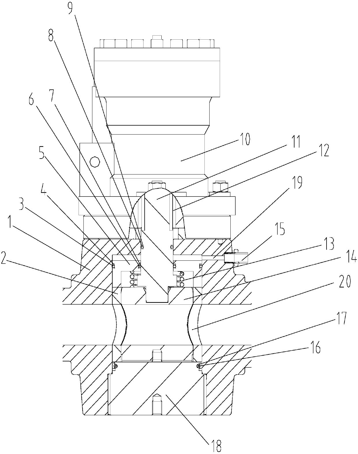
[0017] Such as figure 1 Shown: an anti-sand accumulation plug valve, including a valve body 1, a bonnet 18 and a cock rod 11 arranged in the valve body 1, the valve body 1 and the bonnet 18 are connected by threads, and the lower end of the cock rod 11 The upper end of the valve body 1 is provided with a driver 10, the driver 10 is connected to the valve body 1 by bolts, and the driver 10 is connected to the cock rod 11 through a flat key 12 , the driver 10 provides a rotational torque, the driver 10 transmits the torque to the cock rod 11 through the flat key 12, and a cylindrical sealing rubber core 2 is arranged outside the cock 14, and the upper part of the sealing rubber core 2 A piston 5 is set, and an annular sealing cavity is formed between the cock 14, the cock rod 11 and the piston 5, and a spring 13 is arranged in the sealing cavity, and the spring 13 is pressed between the piston 5 and the cock 14 , the piston 5, the cock rod 11, the sealing rubber core 2 and the ...

Embodiment 2

[0019] An anti-sand plug valve, comprising a valve body 1, a bonnet 18 and a cock rod 11 arranged in the valve body 1, the valve body 1 and the bonnet 18 are connected by threads, the lower end of the cock rod 11 and the cylinder The upper end of the valve body 1 is provided with a driver 10, the driver 10 is fastened to the valve body 1 through bolts, the driver 10 is connected to the cock rod 11 through a flat key 12, the The driver 10 provides the rotational torque, and the driver 10 transmits the torque to the cock rod 11 through the flat key 12. A cylindrical sealing rubber core 2 is arranged outside the cock 14, and a piston is arranged on the upper part of the sealing rubber core 2. 5. An annular sealing cavity is formed between the cock 14, the cock rod 11 and the piston 5, and a spring 13 is arranged in the sealing cavity, and the spring 13 is pressed between the piston 5 and the cock 14, and the The piston 5, the cock rod 11, the sealing rubber core 2 and the cock 14...


PUM


Abstract

The invention relates to the technical field of oil-gas field construction operation equipment, in particular to an anti-sand-accumulation plug valve which comprises a valve body, a valve cover and aplug rod arranged in the valve body. The valve body is connected with the valve cover; the lower end part of the plug rod is connected with a plug; a driver is arranged on the upper end part of the valve body and is connected with the valve body; the driver transmits a torque to the plug rod through a flat key; a sealing rubber core is arranged on the outer part of the plug; a piston is arranged on the upper part of the sealing rubber core; an annular seal cavity is formed among the plug, the plug rod and the piston; a spring is arranged in the seal cavity; the piston, the plug rod, the sealing rubber core and the plug are located in an inner core of the valve body; the inner core of the valve body communicates with an oil passage; and the oil passage is filled with hydraulic oil for driving the piston to move up and down. According to the anti-sand-accumulation plug valve provided by the invention, a gap between the sealing rubber core and the plug can be adjusted, and no gap exists among the plug, the sealing rubber core and the valve body during a pressure-bearing and fluid conveying process, so that sand is prevented from being accumulated.

Description

technical field [0001] The invention relates to the technical field of oil and gas field construction equipment, in particular to an anti-sand accumulation plug valve. Background technique [0002] The structure and principle of the existing cock valve are: the sealing parts of the existing cock valve are mainly metal valve body, metal cock, metal sealing arc and non-metallic seal, the inner side of the cock and sealing arc and the valve body and The outside of the sealing arc needs to be sealed. The valve body, cock and sealing arc are all designed with flow channel holes of the same size. When the axes of the flow channel holes of the three are collinear, the cock valve is in the open state. When the cock rotates 90 degrees around its axis, the flow channel of the cock The hole, the arc and the flow channel hole of the valve body are in a vertical state, and the plug valve is closed. [0003] The shortcomings and deficiencies of the existing cock valve mainly include the...

Claims


Application Information

Patent Timeline
Patent Type & Authority Applications(China)
IPC IPC(8): F16K5/04F16K5/08F16K5/18F16K41/02
CPCF16K5/0407F16K5/0471F16K5/0485F16K5/188Y02E10/20
Inventor 黄金领王新明李建福张树林李帅任光辉
Owner YANTAI JEREH PETROLEUM EQUIP & TECH CO LTD
Why Eureka
Try Eureka