Full-automatic non-demoulded glove cleaning machine

A cleaning machine, fully automatic technology, applied in the direction of household components, household appliances, other household appliances, etc., can solve the problems of demoulding failure, poor equipment adaptability, large demoulding force, etc., to achieve convenient and flexible use and high demoulding efficiency. , The effect of enhancing the demolding strength

Pending Publication Date: 2019-05-21
ZIBO REEBOW AUTOMATION EQUIP CO LTD
View PDF0 Cites 5 Cited by
  • Summary
  • Abstract
  • Description
  • Claims
  • Application Information

AI Technical Summary

Problems solved by technology

However, there are still many defects in the actual use of the existing brush-type demoulding machine, and the demoulding effect is not satisfactory
[0003] First of all, the cross-section of the brush of the existing brush-type demoulding equipment is cylindrical, and the contact surface between the brush and the glove is in linear contact during demoulding, and the outer working surface of the brush is curved, resulting in sparse distribution and small contact area , resulting in a smaller demoulding force. Generally, only semi-demolding gloves can be demolded, and often the demoulding is not complete or the demou

Method used


Image

  • Full-automatic non-demoulded glove cleaning machine
  • Full-automatic non-demoulded glove cleaning machine
  • Full-automatic non-demoulded glove cleaning machine

Examples


Embodiment 1

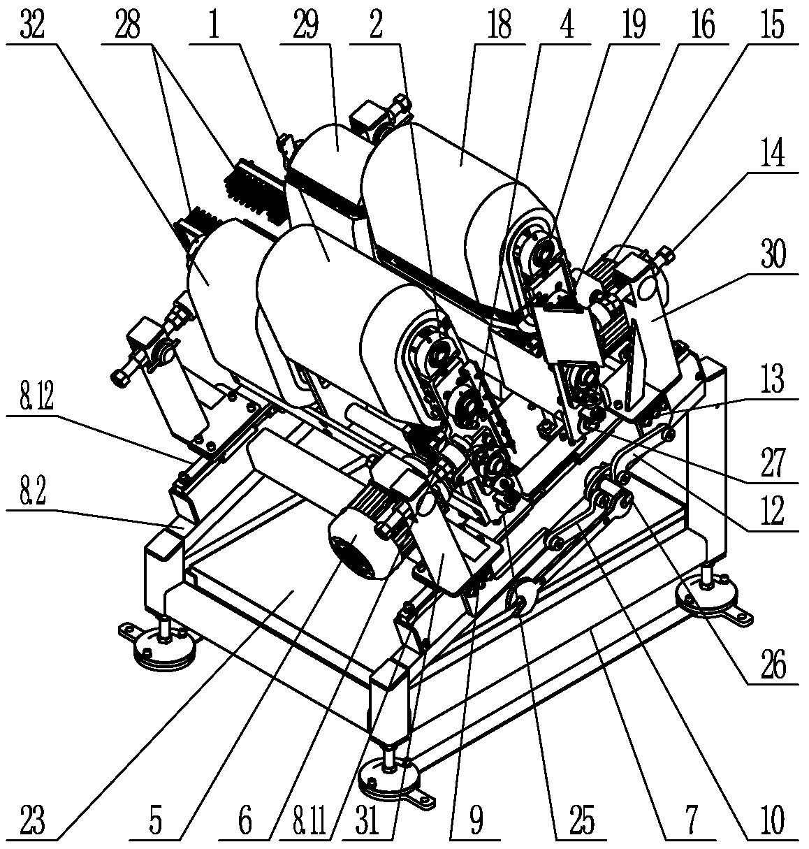
[0047] Such as figure 1 As shown, a full-automatic non-release glove cleaning machine according to the present invention includes a base 7, a sliding track device 8, a high-position demoulding assembly, a low-position demoulding assembly and a sliding drive assembly, and the sliding The rail device 8 is installed on the base 7, and the high-position demoulding assembly and the low-position demoulding assembly are installed on the sliding rail device 8, and both the high-position demoulding assembly and the low-position demoulding assembly include at least one set of brush functional groups. In this embodiment, both the high-position demoulding component and the low-position demoulding component include two brush functional groups.

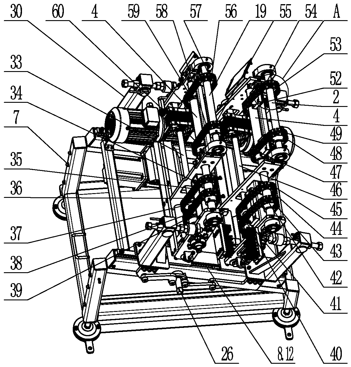
[0048] Such as figure 2 and 4 As shown, the brush function group of the high-position demoulding assembly is called a high-position brush function group, and the high-position brush function group includes a high-position brush bracket 17, a hig...

Embodiment 2

[0068] The difference between this embodiment and Embodiment 1 is that the high-position demoulding assembly only includes one to two sets of high-position upper annular brush mechanisms 18, and does not include the high-position lower annular brush mechanism 29; The lower upper annular brush mechanism 1 with the same number of components also does not include the lower lower annular brush mechanism 32 .

[0069] In this embodiment, the high-position upper annular brush mechanism 18 and the low-position upper annular brush mechanism 1 can use the same scrubber structure as in Embodiment 1, or can be set as a strip structure.

[0070] The ring-shaped brush mechanism 18 on the high position of the strip structure is specifically set as follows:

[0071] Install the high position first lower pulley on the shaft 16 in the high position, install the high position first upper pulley on the high position installation shaft 19, and set the high position upper ring wool on the high pos...

Embodiment 3

[0077] The difference between this embodiment and embodiment one and embodiment two is:

[0078] The sliding drive assembly includes a high-position drive cylinder and a low-position drive cylinder. Both the high-position drive cylinder and the low-position drive cylinder are installed on the track support 8.2. Hinged low slider 9.


PUM


Abstract

The invention discloses a full-automatic non-demoulded glove cleaning machine, and belongs to the field of glove demoulding equipment. The full-automatic non-demoulded glove cleaning machine is characterized in that a base, a sliding track device, a high-position demoulding assembly, a low-position demoulding assembly and a sliding driving assembly are included; the sliding track device is arranged on the base, the high-position demoulding assembly and the low-position demoulding assembly are arranged on the sliding track device, and each of the high-position demoulding assembly and the low-position demoulding assembly comprises at least one brush function set; the sliding driving assembly can drive the high-position demoulding assembly and the low-position demoulding assembly to get closeto each other, and the brush function sets of the high-position demoulding assembly and the low-position demoulding assembly can conduct opposite clamping and rotating for stripping of a glove on a hand die. According to the full-automatic non-demoulded glove cleaning machine, a plate brush type demoulding plane is arranged, high demoulding strength is provided by increasing the contact area, brushes are fixed to a chain through a plate structure, the density of the brushes on the glove contact face is guaranteed, and the demoulding strength is effectively improved. Equipment can adapt to thehalf demoulding work and can also be applicable to the non-demoulding work, and the demoulding efficiency is higher.

Description

technical field [0001] The invention belongs to the field of glove demoulding equipment, in particular to a demoulding equipment for disposable plastic gloves. Background technique [0002] The plastic glove stripping machine is generally designed in the form of a pneumatic stripping structure or a brush stripping structure. The structure of the pneumatic stripping machine is relatively complicated. It is necessary to set up a crimping mechanism to roll up the wrist of the glove, and then use the manipulator to clamp the crimping outer support, and finally blow the glove from the hand mold by high-pressure airflow. Pneumatic demoulding machines need to use high-pressure compressed air, which not only consumes a lot of energy but also brings about a lot of noise pollution. The advantage of the brush-type mold release structure is that the equipment structure is relatively simple, and the glove is removed from the hand mold by the friction of the rotating brush. But existing...

Claims


Application Information

Patent Timeline
IPC IPC(8): B29C41/42B29L31/48
Inventor 徐云海徐云涛周军华朱序良党金梗
Owner ZIBO REEBOW AUTOMATION EQUIP CO LTD
Why Eureka
Try Eureka