Magneto-optic imaging nondestructive testing device

A magneto-optical imaging and non-destructive testing technology, which is applied in the direction of measuring devices, optical testing flaws/defects, material magnetic variables, etc., can solve the problems of not being able to determine the internal thermal state of the workpiece, requiring couplants, and expensive prices, etc., to achieve non-contact Non-destructive testing, safe and reliable operation, and high degree of automation

Pending Publication Date: 2017-05-31
GUANGDONG UNIV OF TECH
View PDF12 Cites 7 Cited by
  • Summary
  • Abstract
  • Description
  • Claims
  • Application Information

AI Technical Summary

Problems solved by technology

This method is difficult to distinguish different types of defects, and its biggest disadvantage is that it needs a coupling agent for detection.
Magnetic particle testing is limited to ferromagnetic materials and has strict requirements on the surface of the workpiece; penetrant testing is limited to surface opening defects; radiographic testing is expensive and the testing equipment is large, and the radiation generated is extremely harmful to the human body; ultrasonic testing has requirements for operators Higher, it is difficult to distinguish different types of defects and a couplant is required; eddy current testing is only suitable for the detection of the surface and near-surface of conductive materials, and it is difficult to judge the type, shape and size of workpiece defects; laser holographic nondestructive testing depends on the inside of the object Whether the defect of the object can cause the corresponding deformation of the surface of the object under the action of external force; the acoustic emission detection technology is generally weak due to the strength of the acoustic emission signal, and it needs to be detected with the help of sensitive electronic instruments; the infrared detection technology mainly measures the thermal state of the workpiece surface, which cannot be determined The thermal state inside the workpiece, which is expensive compared with other inspection instruments or conventional monitoring equipment

Method used


Image

  • Magneto-optic imaging nondestructive testing device
  • Magneto-optic imaging nondestructive testing device
  • Magneto-optic imaging nondestructive testing device

Examples


Embodiment Construction

[0024] The present invention will be described in further detail below in conjunction with the accompanying drawings.

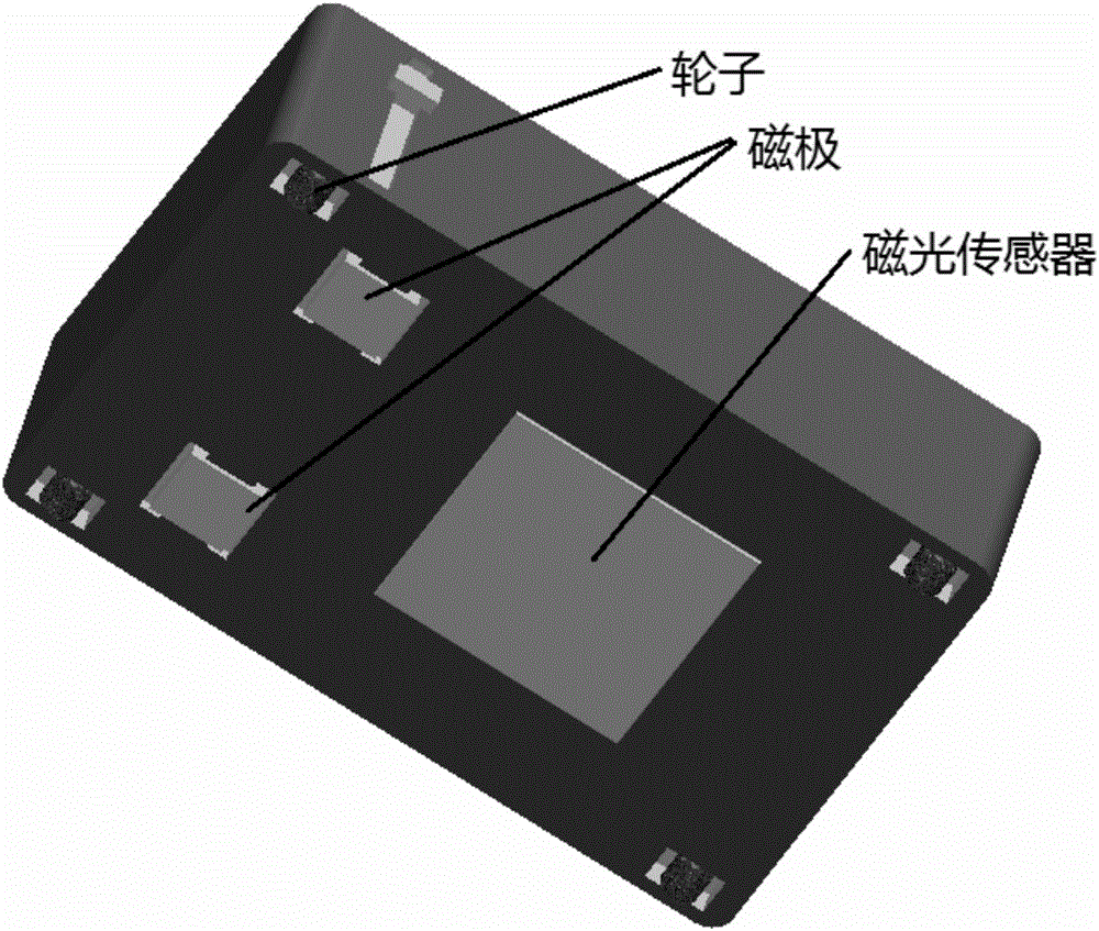
[0025] The present invention uses the Faraday magneto-optical effect principle: when a beam of polarized light passes through the medium, if there is an external magnetic field in the beam propagation direction, the polarized light will be deflected when it passes through the polarization plane, and the deflection angle depends on the strength of the magnetic field.

[0026]The invention applies the magneto-optical imaging technology, and the electromagnet is excited by a magnetic field generator with a constant current or an alternating current to induce a magnetic field on the workpiece, and the distribution of the magnetic field will be distorted at the defect of the workpiece, causing the vertical magnetic field component there to occur. changes, and correspondingly changes the induced magnetic field. The magneto-optical imaging sensor produces a magneto-...


PUM


Abstract

The invention discloses a magneto-optic imaging nondestructive testing device. The device can be used for detecting defects of a workpiece, such as, detecting the quality of a mold casting and the working state of the casting in use. The device comprises a direct current port, an alternating current port, a controller, a magnetic field generator, a magneto-optic imaging sensor and a computer, wherein the magnetic field generator is electrically connected with the direct current port and the alternating current port through the controller; the direct current port is used for accessing direct current to the magnetic field generator; the alternating current port is used for accessing alternating current to the magnetic field generator; the magnetic field generator is used for supplying excitation to the workpiece according to a control signal of the controller; the magneto-optic imaging sensor is used for collecting a magneto-optic image of the workpiece and sending to the computer; and a distance between a magnetic pole of the magnetic field generator and the workpiece is adjusted through a blocking slot.

Description

technical field [0001] The present invention relates to the detection field of workpieces, in particular to a magneto-optical imaging non-destructive testing device based on a constant magnetic field and an alternating magnetic field, which is specifically applied to the defect detection of workpieces, for example, to detect the quality of molded castings, and to detect the quality of castings in use Working status, which includes micro scratches, depressions, slag inclusions, cracks on the surface of the workpiece, and incomplete penetration, fusion, burn-through, welding bumps, pores, undercuts, arc craters and other defects during the welding process. Background technique [0002] Automobiles, aerospace, ships, etc. all use a large number of metal castings, and metal products are closely related to our lives. Due to the influence of various random interference factors such as harsh working conditions, heavy workload and high quality requirements, castings will inevitably ...

Claims


Application Information

Patent Timeline
Patent Type & Authority Applications(China)
IPC IPC(8): G01N27/83G01N21/88
CPCG01N21/8806G01N21/8851G01N27/83G01N2021/8887G01N2021/8848G01N2021/8854
Inventor 高向东马女杰
Owner GUANGDONG UNIV OF TECH
Why Eureka
Try Eureka