Oil conveying pipeline leakage monitoring method based on negative pressure wave method and flow trend method

An oil pipeline and negative pressure wave technology, which is applied in the field of oil pipeline leakage monitoring based on negative pressure wave method and flow trend method, can solve the problems of reducing system reliability, increasing workload, and low accuracy, and achieve good economic benefits and social benefits, high A/D conversion accuracy, and high sensitivity effects

Active Publication Date: 2018-05-15
廊坊市蓝德采油技术开发有限公司
View PDF9 Cites 20 Cited by
  • Summary
  • Abstract
  • Description
  • Claims
  • Application Information

AI Technical Summary

Problems solved by technology

4) The instantaneous flow rate of the receiving station drops
5), resulting in a loss
The system cannot shield or give accurate prompts. It needs to be eliminated after the pressure change is located. However, due to the complex and frequent pressure changes, false alarms are caused.
Only based on the above conditions, the source of the change of the leakage condition cannot be accurately judged, and if an alarm is triggered, it is necessary to eliminate the alarm caused by the operation of the site according to the positioning results and verify with other sites, which reduces the reliability of the system and increases unnecessary workload.
The traditional single pressure transmitter and flow mode cannot accurately judge the alarm caused by the operation in the station or the process condition change of the station, and cannot shield or accurately prompt the alarm caused by the action of the station, resulting in poor stability and low accuracy of the leakage monitoring system. Aiming at the above problems, a method of oil pipeline leakage monitoring based on negative pressure wave method and flow trend method is proposed

Method used


Image

  • Oil conveying pipeline leakage monitoring method based on negative pressure wave method and flow trend method
  • Oil conveying pipeline leakage monitoring method based on negative pressure wave method and flow trend method
  • Oil conveying pipeline leakage monitoring method based on negative pressure wave method and flow trend method

Examples


Embodiment 1

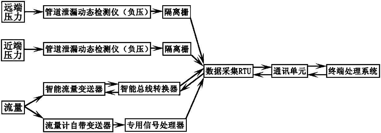
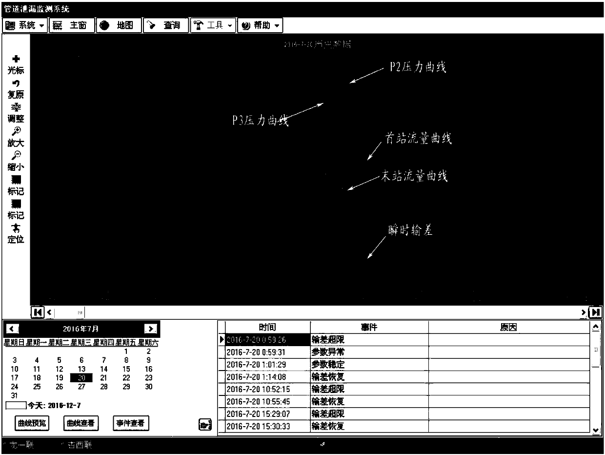
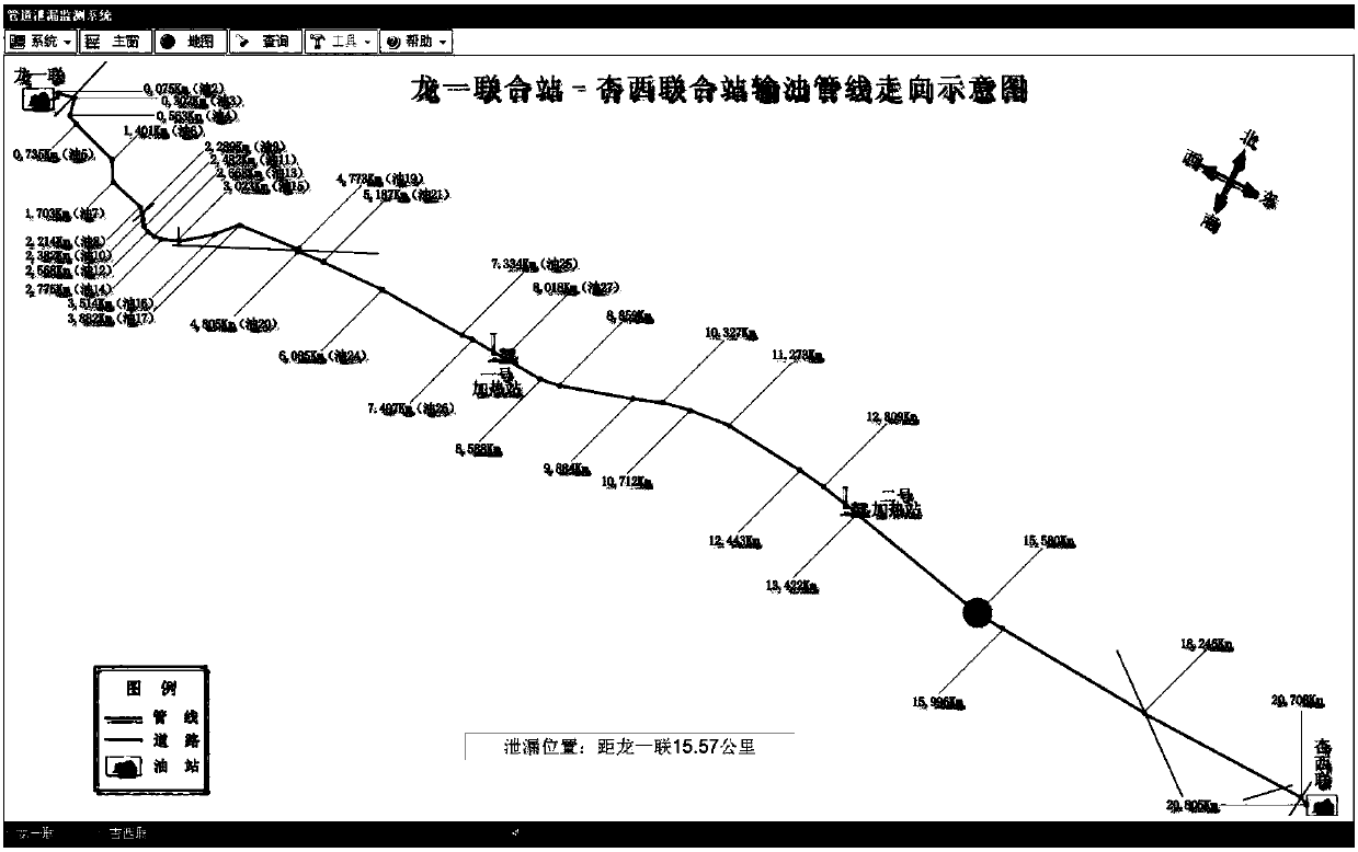
[0040] When applied to the No. 9 Oil Production Plant of Daqing Oilfield, among them, the pipeline profile, such as Figure 2-3 As shown, the oil pipeline from Longyilian (first station) to Xingxilian (last station) has a pipe diameter of ф219mm and a total length of 23Km, with a daily crude oil output of 1000m3, using continuous oil transportation. 1. The first station (Longyilian): One pressure transmitter (P1) installed at the outlet of the output flow, one pressure transmitter (P2) installed 20 meters away from the last station, and the signal cable leads to the first station Data acquisition unit; 2. The last station (Xingxilian): install one pressure transmitter (P4) at the inlet of the manifold of the five oil pipelines, and install one pressure transmitter (P3) at 20 meters in the direction of the first station. The cable is led to the data acquisition unit of the last station; 3. The first and last stations: respectively install a set of data acquisition devices and a...


PUM


Abstract

The invention discloses an oil conveying pipeline leakage monitoring method based on a negative pressure wave method and a flow trend method. The monitoring method is characterized in that a system monitoring terminal, data acquiring units, communication units, a field instrument and monitoring system software are arranged, wherein the field instrument comprises flow meters and pressure transmitters; the pressure transmitters are mounted at an outlet pipeline of the flow meter in an exit, and the pipeline between the pressure transmitters is not less than 20m; another two pressure transmittersare mounted at an inlet pipeline of the flow meter in an entrance, and the pipeline between the pressure transmitters is not less than 20m; the data acquiring units are mounted at the exit and the entrance and used for acquiring the station double pressure and flow data in real time and preprocessing the data; the communication units are mounted at the exit and the entrance and used for encapsulating the data processed by the data acquiring units and then transmitting to the system monitoring terminal. With the adoption of the method, the operation variation of a station can be accurately determined, thus the alarm caused by the operation in the station can be shielded or accurately promoted, so that the stability and the accuracy of a leakage monitoring system can be improved.

Description

technical field [0001] The invention relates to a method for monitoring leakage of an oil pipeline, in particular to a method for monitoring leakage of an oil pipeline based on a negative pressure wave method and a flow trend method, and belongs to the technical field of application of monitoring methods for oil pipelines. Background technique [0002] At present, when a pipeline leaks, due to the pressure difference inside and outside the pipeline, the liquid in the pipeline will flow out, the pressure at the leak will drop suddenly, and the liquid around the leak will replenish to the leak due to the pressure difference, and a negative pressure fluctuation will suddenly form in the pipeline. . The negative pressure wave propagates from the leakage point to the upper and lower ends of the pipeline. At the same time, the flow balance in the pipeline is broken, resulting in a transmission difference, the instantaneous flow at both ends changes, the flow at the output end inc...

Claims


Application Information

Patent Timeline
Patent Type & Authority Applications(China)
IPC IPC(8): F17D5/06
CPCF17D5/06
Inventor 陈俐孟庆禹黄鹏冯浩凌黄鸣李科熳
Owner 廊坊市蓝德采油技术开发有限公司
Why Eureka
Try Eureka