
FPGA aging test system and circuit configuration method thereof

A test system and circuit configuration technology, applied in the direction of measuring electricity, measuring devices, measuring electrical variables, etc., can solve the problems of FPGA volatility, loss of chip functions, poor compatibility, etc., to ensure safety, fewer terminals, and reasonable definite effect

Inactive Publication Date: 2018-05-15
EHIWAY MICROELECTRONIC SCI & TECH SUZHOU CO LTD
View PDF5 Cites 10 Cited by
  • Summary
  • Abstract
  • Description
  • Claims
  • Application Information

AI Technical Summary

Problems solved by technology

[0004] The burn-in test for FPGA has become an optional reliability test to ensure the pass rate of FPGA. Compared with other monolithic integrated circuits, FPGA is volatile and requires special non-volatile devices to store configuration information. FPGA It needs to be configured before working, and the function will be lost after the chip is powered off
[0005] Based on the wide application of FPGA, there are various test systems and methods for burn-in tests on various FPGA devices. Different test systems and methods may be poorly compatible, cumbersome and time-consuming, so it is urgent It is necessary to propose a general-purpose FPGA burn-in test system with a simple structure and suitable for process-based mass production

Method used


Image

  • FPGA aging test system and circuit configuration method thereof
  • FPGA aging test system and circuit configuration method thereof
  • FPGA aging test system and circuit configuration method thereof

Examples


Embodiment Construction

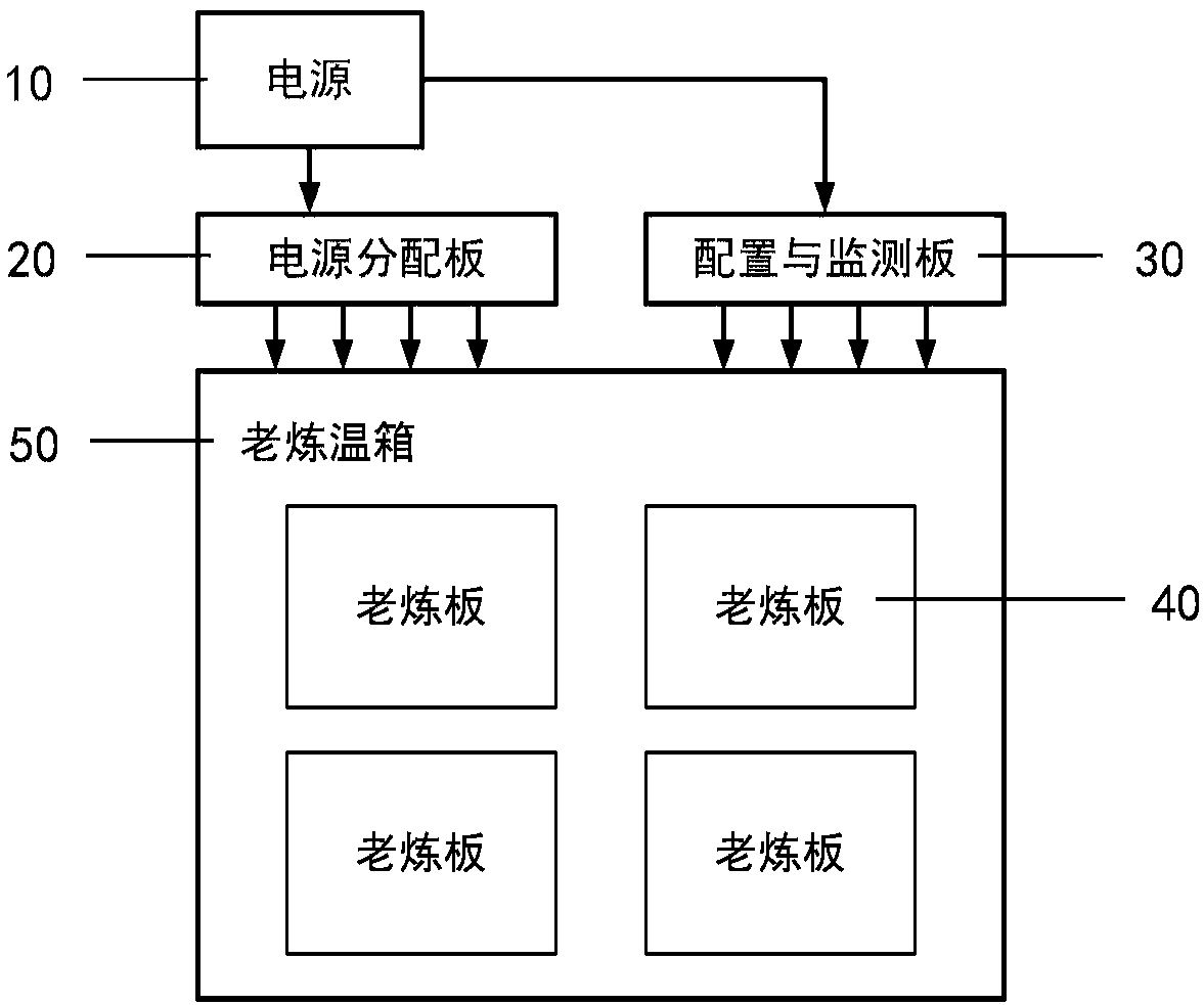
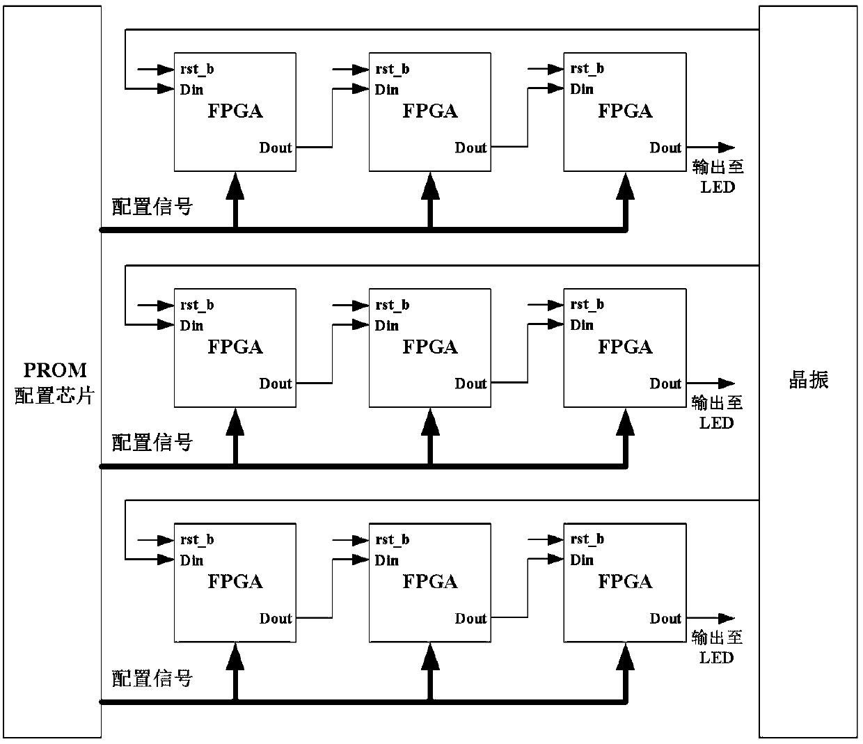
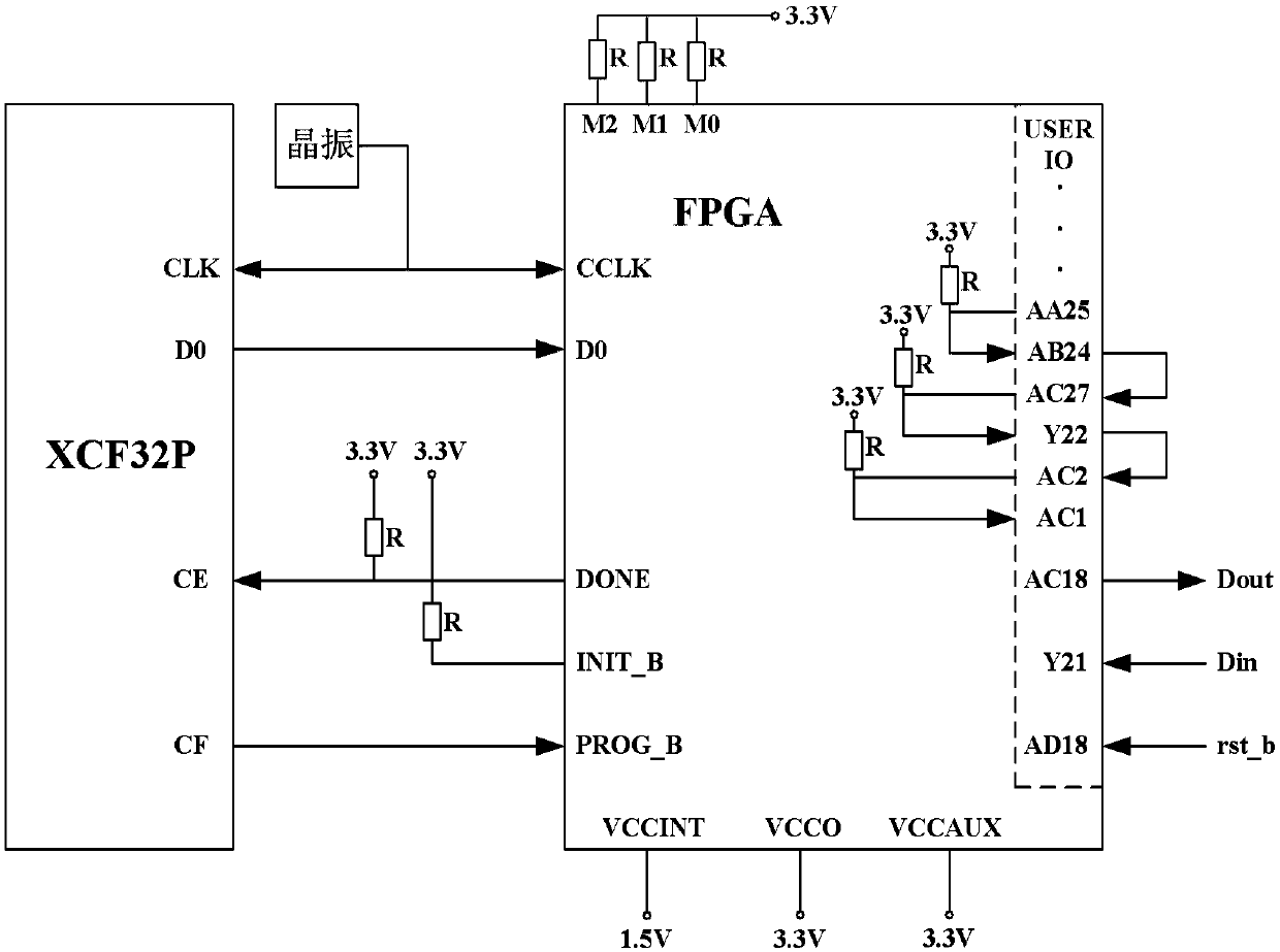
[0034] The present disclosure provides an FPGA burn-in test system and its circuit configuration method, based on a programmable read-only memory (PROM, Programmable Read-Only Memory) configuration method, adopting a passive serial configuration mode, through configuration and monitoring outside the incubator The board configures the FPGA, and the status of the device during the burn-in process can be monitored in real time; according to the rich characteristics of the built-in IP core of the FPGA device, the burn-in circuit is designed, and the working frequency of the burn-in circuit is reasonably determined through the calculation of the device junction temperature. There are few lead-out terminals on the board, and the connection structure with the outside of the incubator is simple and convenient; the burn-in test system can adaptively update the configuration circuit according to the needs of the FPGA chip, and is suitable for different FPGA chips in the same package, whic...


PUM


Abstract

The invention discloses an FPGA aging test system and a circuit configuration method thereof. The FPGA aging test system comprises multiple aging boards, a power distribution board and a configurationand monitoring board, wherein the multiple aging boards are placed in an aging temperature box, each aging board comprises a plurality of FPGA chip sockets, a power supply interface and a crystal vibrator, and excitation is provided for the aging board; the power distribution board is placed outside the aging temperature box and provides multi-way independent power for each aging board; and the configuration and monitoring board is arranged outside the aging temperature box and comprises a PROM configuration chip. In the aging test, a plurality of different FPGA chips are placed in the FPGA chip sockets in the aging board and through the PROM configuration chip of the configuration and monitoring board, one PROM is controlled to simultaneously configure the plurality of different FPGA chips in a passive serial mode. The system is applicable to different FPGA chips with the same packaging, universality is realized, the number of required nonvolatile storage devices is saved, and through introducing a state monitoring system and safety assurance measures, the chip state during the aging process can be monitored in real time.

Description

technical field [0001] The disclosure belongs to the technical field of integrated circuits, and relates to an FPGA burn-in test system and a circuit configuration method thereof. Background technique [0002] FPGA has the advantages of programmable, high integration, high speed and high reliability. By configuring the logic functions and input / output ports inside the device, the original circuit board-level design is placed in the chip, which improves circuit performance, reduces circuit volume, reduces circuit power consumption, and effectively improves design flexibility. and efficiency. [0003] At present, integrated circuits have been widely used in aviation, military, industrial and other industries, and their reliability has become a major consideration for the wide application of devices. As one of the most important reliability tests, burn-in test is a method to make products A method of working under stress for a period of time to stabilize its properties. The ...

Claims


Application Information

Patent Timeline
IPC IPC(8): G01R31/3185
CPCG01R31/318519
Inventor 张超杨海钢赵川胡凯齐振飞吴玉志
Owner EHIWAY MICROELECTRONIC SCI & TECH SUZHOU CO LTD
Learn More