Beaker capable of achieving mobile stirring

A stirring rod and cup bottom technology, applied in the field of practical room equipment, to shorten the heating time, reduce heat loss, and save alcohol energy

Inactive Publication Date: 2018-05-18
河南大松仪器设备有限公司
View PDF0 Cites 0 Cited by
  • Summary
  • Abstract
  • Description
  • Claims
  • Application Information

AI Technical Summary

Problems solved by technology

[0003] The existing beaker can only be stirred by rotating or moving up and down. When rotating, the cylindrical stirring rod can only rotate in the original position, but cannot move to other directions to achieve stirring.

Method used


Image

  • Beaker capable of achieving mobile stirring
  • Beaker capable of achieving mobile stirring

Examples


Embodiment 1

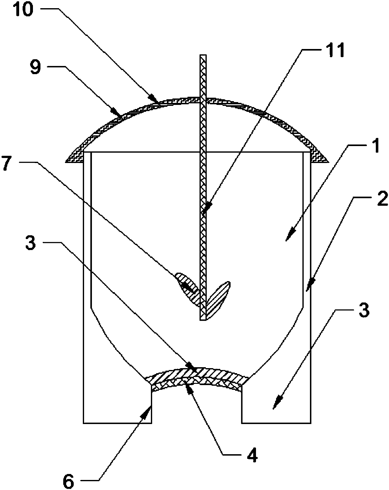
[0028] The technical solution of this embodiment is: a beaker capable of moving and stirring, including a beaker body 1, the side wall of the beaker body 1 is a first vacuum cavity 2, and the bottom of the beaker body 1 protrudes into the beaker body 1 to form an arc shaped cup bottom 3, the edge of the curved cup bottom 3 is integrated with the side wall of the beaker body 1, and the side wall of the beaker body 1 is arranged tangentially with the upper edge of the curved cup bottom 3;

[0029] The bottom of the beaker body 1 is provided with an annular seat 5, the inner diameter of the annular seat 5 is equal to the length of the arc-shaped cup bottom 3 in the horizontal direction, and a carbon black filter screen 4 is arranged in the ring of the annular seat 5, and the carbon black filter screen 4 is detachable connected to the inner wall of the ring seat 5;

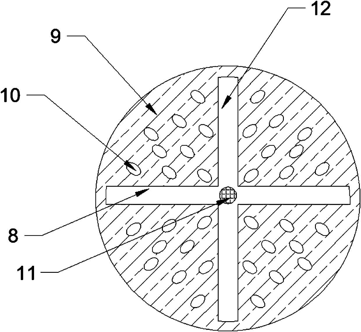
[0030] The upper end of the beaker body 1 is threadedly connected with an arc-shaped cover body 9, and a cylindrica...

Embodiment 2

[0038] Based on the first embodiment, the technical solution of this embodiment is: the carbon black filter 4 is closely attached to the bottom of the arc-shaped cup bottom 3 .

[0039] Such as figure 1 As shown, the carbon black filter screen 4 is closely attached to the bottom of the curved cup bottom 3, so that the filtered flame can directly heat the curved cup bottom 3 after passing through the carbon black filter screen 4.

Embodiment 3

[0041] Based on the first embodiment, the technical solution of this embodiment is: a second vacuum chamber 6 is formed between the inner ring and the outer ring of the annular seat 5 .

[0042] Such as figure 1 As shown, the second vacuum cavity 6 is used in the process of the flame propagating to the arc-shaped cup bottom 3, heat energy is dissipated through the annular seat 5, and the heat of the arc-shaped cup bottom 3 is prevented from being transferred to the outside of the beaker body 1 and dissipated.


PUM


Abstract

The invention discloses a beaker capable of achieving mobile stirring. The beaker comprises a beaker body, a first vacuum cavity is formed in the side wall of the beaker body, and the bottom of the beaker body protrudes into the beaker body to form an arc beaker bottom; an annular base is arranged at the bottom of the beaker body, the inner diameter of the annular base is equal to the length of the arc beaker bottom in the horizontal direction, a carbon black filter screen is arranged in a ring of the annular base, and the carbon black filter screen is detectably connected to the inner side wall of the annular base; an arc cover body is in threaded connection with the upper end of the beaker body, a cylindrical stirring rod vertically penetrates through the arc cover body, one end of the cylindrical stirring rod extends into the beaker body and is fixedly connected with two stirring blades, and horizontal holes are formed in the arc cover body; a first through hole groove and a secondthrough hole groove which are perpendicular to each other are formed in the arc cover body, and the cylindrical stirring rod penetrates through the first through hole groove and the second through hole groove. The cylindrical stirring rod can move to the edge of the beaker body, and accordingly materials in the beaker body are sufficiently mixed or sufficiently reacted.

Description

technical field [0001] The invention belongs to the technical field of equipment for practical rooms, and in particular relates to a beaker capable of being moved and stirred. Background technique [0002] A beaker is a common laboratory glassware, usually made of glass, plastic or heat-resistant glass. The beaker is cylindrical with a notch on one side of the top for easy pouring. Some beakers are also marked with a scale on the outer wall, which can roughly estimate the volume of the liquid in the beaker. [0003] Existing beakers can only be stirred by rotating or moving up and down. When rotating, the cylindrical stirring rod can only rotate on the original position, but cannot move to other directions to achieve stirring. Contents of the invention [0004] The object of the present invention is to address the problems described above, and the present invention provides a beaker that can be moved and stirred. [0005] The technical scheme that the present invention ...

Claims


Application Information

Patent Timeline
Patent Type & Authority Applications(China)
IPC IPC(8): B01L3/00B01F15/06B01F15/00B01F7/18
CPCB01L3/508B01F27/90B01F35/511B01F35/92
Inventor 刘真
Owner 河南大松仪器设备有限公司
Why Eureka
Try Eureka