Automatic machining equipment of cylindrical shell

A technology of automatic processing and cylindrical shell, applied in the direction of metal processing, other manufacturing equipment/tools, manufacturing tools, etc., can solve the problems of complicated steps, large occupation area, increased production cost, etc.

Inactive Publication Date: 2018-05-18
ZHEJIANG UNIV OF TECH FENGHUA SMART ECONOMY RES INST
View PDF0 Cites 4 Cited by
  • Summary
  • Abstract
  • Description
  • Claims
  • Application Information

AI Technical Summary

Problems solved by technology

[0002] In people's life, whether it is food or daily necessities, packaging boxes are used. One of the common packaging boxes is cylindrical. In the production process of the cylindrical shell, the large production line can complete its automatic production. However, this large-scale production line has a complex structure, a large footprint, and high equipment costs. It is only suitable for some large-scale factories, and some small manufacturers can only use a variety of machines to complete the processing and production of cylindrical shells, making the production process complicated. As a result, its production efficiency is reduced and its production cost is increased. In view of the above problems, an automatic processing equipment for cylindrical shells is provided to solve these problems

Method used


Image

  • Automatic machining equipment of cylindrical shell
  • Automatic machining equipment of cylindrical shell
  • Automatic machining equipment of cylindrical shell

Examples


Embodiment Construction

[0027] Below in conjunction with accompanying drawing and embodiment of description, specific embodiment of the present invention is described in further detail:

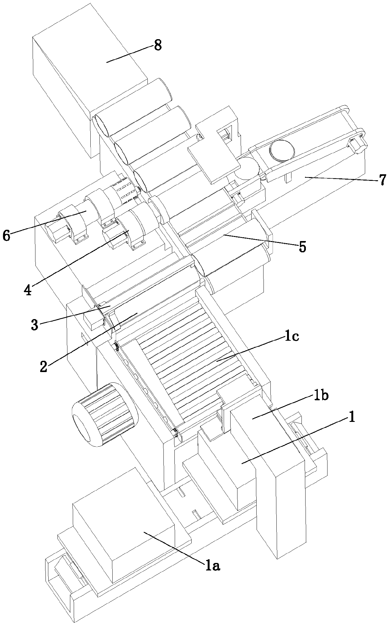
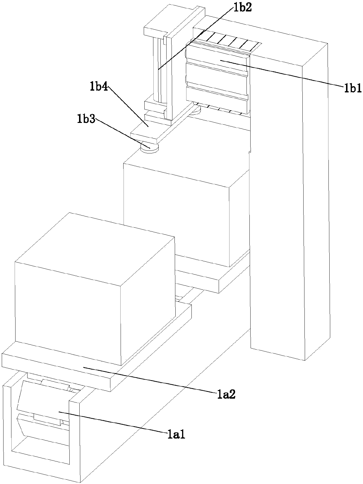
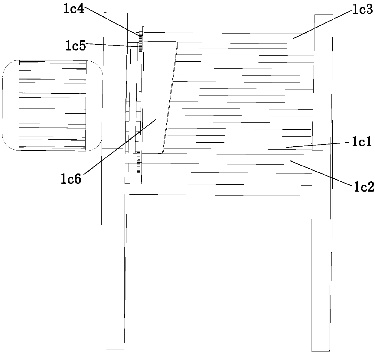
[0028] refer to Figure 1 to Figure 13The shown automatic processing equipment for a cylindrical shell includes a sheet metal feeding device 1, a reel device 2, a conveying device 3, a welding device 4, a conveying device 5, a grinding device 6 and a bottom shell feeding device 7, the The reel device 2 is located at the end of the metal sheet feeding device 1, the conveying device 3 is located at the upper end of the reel device 2, one end of the conveying device 5 is located at the side of one end of the reel device 2, the grinding device 6, the welding device 4 and the bottom shell The feeding device 7 is located on the side of the conveying device 3, and the reel device 2 includes a sizing column 2a, a sizing shell 2b, a fixed frame 2c, a conveying roller 2d and a driven roller 2e, and the sizing column 2a is arr...


PUM


Abstract

The invention relates to the field of mechanical equipment, in particular to automatic machining equipment of a cylindrical shell. The automatic machining equipment of the cylindrical shell comprisesa sheet metal feeding device, a coiling device, a transporting device, a welding device, a conveying device, a polishing device and a bottom shell feeding device. The coiling device comprises a shaping column, a shaping shell, a fixing frame, a conveying roller and a driven roller. The lower end of the shaping column is provided with a top plate. The fixing frame is provided with a first motor used for driving the conveying roller. The output end of the first motor penetrates the fixing frame to be in transmission connection with one end of the conveying roller. A gap between the shaping shelland the shaping column is gradually changed in the direction close to the conveying device to form a circular ring. According to the automatic machining equipment of the cylindrical shell, automaticmachining of the cylindrical shell is achieved through cooperation of the sheet metal feeding device, the coiling device, the transporting device, the welding device, the conveying device, the polishing device and the bottom shell feeding device, the demand for manual labor is reduced, the production cost is reduced, the production efficiency is improved, and the production steps are optimized.

Description

technical field [0001] The invention relates to the field of mechanical equipment, in particular to an automatic processing equipment for cylindrical shells. Background technique [0002] In people's life, whether it is food or daily necessities, packaging boxes are used. One of the common packaging boxes is cylindrical. In the production process of the cylindrical shell, the large production line can complete its automatic production. However, this large-scale production line has a complex structure, a large footprint, and high equipment costs. It is only suitable for some large-scale factories, and some small manufacturers can only use a variety of machines to complete the processing and production of cylindrical shells, making the production process complicated. As a result, the production efficiency is reduced and the production cost is increased. In view of the above problems, an automatic processing equipment for cylindrical shells is provided to solve these problems. ...

Claims


Application Information

Patent Timeline
Patent Type & Authority Applications(China)
IPC IPC(8): B23P23/06B23Q7/00
CPCB23P23/06B23Q7/00
Inventor 李伟
Owner ZHEJIANG UNIV OF TECH FENGHUA SMART ECONOMY RES INST
Why Eureka
Try Eureka