[0012] In order to make the object, technical solution and advantages of the present invention clearer, the present invention will be further described in detail below in conjunction with the accompanying drawings and embodiments. It should be understood that the specific embodiments described here are only used to explain the present invention, not to limit the present invention.
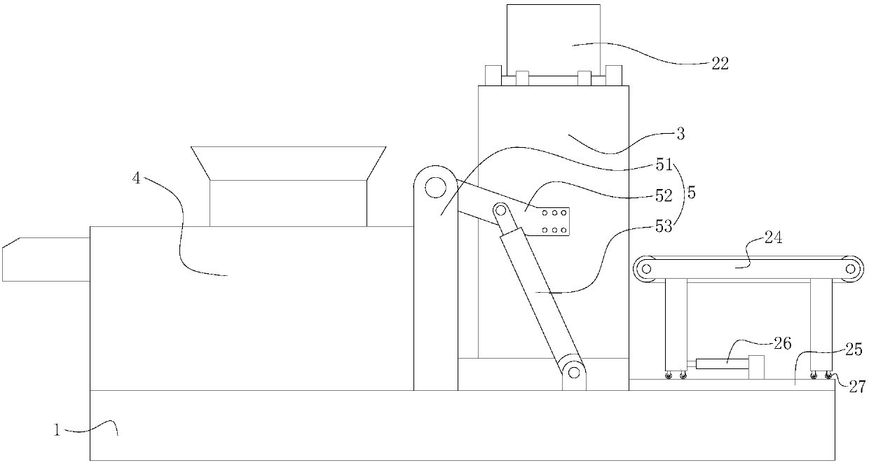
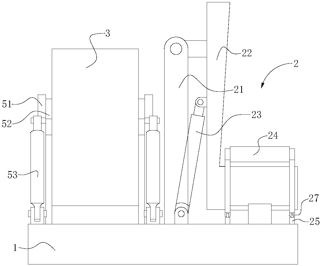
[0013] like figure 1 , figure 2 As shown, the present invention provides a clip finishing system, including a base 1, a feeding mechanism 2, an eddy current finishing machine 3, a vibrating screen 4 and a turning mechanism 5, and the eddy current finishing machine 3 of this embodiment can use ZHMLD50 Type, ZHMLD120 or ZHMLD250, and other types of finishing machines can also be used according to needs. In this embodiment, the base 1 is laid horizontally on the ground, and the feeding mechanism 2 , the vortex finishing machine 3 , the vibrating screen 4 and the turning mechanism 5 are all arranged on the base 1 .
[0014] like Figure 1~3 As shown, the feeding mechanism 2 of this embodiment includes a feeding bracket 21, a hopper 22, a feeding hydraulic cylinder 23, and a feeding conveyor belt 24; the feeding bracket 21 is vertically arranged on the eddy current finishing machine 3- side, and its lower end is fixed on the base 1; the upper hopper 22 includes an upper hopper body 221 and a slideway 222 formed by extending upward from the side wall of the upper hopper 22, the slideway 222 is formed with the content in the upper hopper body 221 The chute 222a connected to the cavity, when the upper hopper 22 rotates at a certain angle, the clip in the upper hopper body 221 can slide out along the chute 222a, when specifically set, the chute 222 of this embodiment can be set to a cross section of U-shaped or arc-shaped, and the discharge end of the slideway 222 is set on the cover plate 223 of the cover chute 222a, which can limit the position of the clip in the chute 222a, thereby preventing the clip from sliding into the eddy current. During the process of decorating machine 2, they collide with each other and pop up; the slideway 222 is hinged to the top of the feeding bracket 21 near the upper end, and one end of the feeding hydraulic cylinder 23 is hinged to the lower end of the loading bracket 21, and the other end is hinged to the lower end of the loading bracket 21. The middle part of the slideway 222 can drive the upper end of the slideway 222 to rotate above the feed port of the eddy current finishing machine 3, and the discharge end of the feed conveyor belt 24 is set close to the upper hopper body 221; When it works, the formed clips are conveyed into the upper hopper body 221 by the feeding conveyor belt 24, when the clips in the upper hopper body 221 reach the set amount or the last batch of clips of the eddy current finishing machine 3 has been completed After the polishing process, the feeding conveyor belt 24 stops feeding, the feeding hydraulic cylinder 23 drives the feeding hopper 22 to rotate relative to the feeding support 21, and the slideway 222 rotates in an inclined state, that is, the loading hopper body 221 is higher than the slideway 222 relative to the feeding support 21, the single piece collected in the hopper body 221 slides into the eddy current finishing machine 3 along the chute 222a on the slideway 222; Continue to feed clips into the upper hopper body.
[0015] In actual application, in order to facilitate the feed conveyor belt 24 to transport clips into the upper hopper body 221, the discharge end of the feed conveyor belt 24 is generally located above the upper hopper body 221, which easily affects the rotation of the upper hopper body 221 with the slideway 222, so The feeding mechanism 2 described in this embodiment also includes a guide rail 25 and a telescopic cylinder 26, so that the guide rail 25 can be set along the conveying direction of the feed conveyor belt 24, the guide rail 25 can be laid on the base 1, and the feed conveyor belt 24 The pulley 27 matched with the guide rail 25 can be set on the side, and the cylinder end of the telescopic cylinder 26 is fixed on the base 1, and its piston rod end is connected with the feed conveyor belt 24. Cylinder 26 drives feeding conveyor belt 24 to move up the hopper body 221 along the guide rail 25 to set a distance, so that the discharge end of feeding conveyor belt 24 matches the feeding end of upper hopper body 221, that is, the feed conveyor belt 24 The clips dropped from the discharge end can be matched and dropped into the upper hopper body 221, and when it is necessary to turn over the feed hopper 22 and dump the clips collected in the vortex finishing machine 3, the telescopic cylinder 26 drives the feeding conveyor belt 24 moves away from the upper hopper body 221 along the guide rail 25, which can prevent the feeding conveyor belt 24 from hindering the turning of the upper hopper 22, and ensure that the materials in the feeding hopper are poured into the vortex finishing machine 3 smoothly.
[0016] After the vortex finishing machine 3 finishes polishing the clips, it can pour the processed clips into the vibrating screen 4, so the vibrating screen 4 described in this embodiment is cooperatingly arranged on the discharge side of the vortex finishing machine 3 , and its lower end is fixed on the base 1, which can separate the impurities in the clip formed after polishing and the mixture of impurities.
[0017] In order to facilitate the eddy current finishing machine 3 to pour the processed clips onto the vibrating screen 4, a turning mechanism 5 is provided in this embodiment, which includes a turning bracket 51, a turning lever 52 and a turning hydraulic cylinder 53, and the turning bracket 51 is vertical. It is directly arranged between the vibrating screen 4 and the vortex finishing machine 3, and its lower end is fixed on the base 1; one end of the turning rod 52 is hinged on the top of the turning bracket 51, and the other end is fixedly connected to the vortex finishing machine. For the decorative machine 3, the piston rod end of the turning hydraulic cylinder 53 is hinged to the middle part of the turning lever 52 and can drive the turning lever 52 to rotate relative to the turning bracket 51; In the straight state, when the clip is toppled over, its open end needs to be slanted downward, so in order to facilitate the driving of the overturning hydraulic cylinder 53, the overturning lever 52 in this embodiment is arranged obliquely and its upper end is hinged to the top and lower ends of the overturning bracket 51 Fixedly connected to the middle part of the eddy current finishing machine 3, the cylinder end of the turning hydraulic cylinder 53 is hinged to the base 1, and the piston rod end is hinged to the turning lever 52 and can drive the turning lever 52 to rotate vertically. In the straight state, that is, when the eddy current finishing machine 3 is being polished, its lower end is supported on the base 1. After the polishing is completed, the turning hydraulic cylinder 53 drives the turning lever 52 to rotate upwards, which can drive the eddy current finishing machine 3 to turn over the support 51 When the top end rotates, when the overturning lever 52 rotates to a roughly vertical state, the eddy current finishing machine 3 rotates at an angle greater than 90°, and makes its opening end obliquely downward, thereby pouring the clip inside it into the vibrating screen 4 . In this embodiment, the turning mechanism 5 is used to drive the eddy current finishing machine 3 to discharge the material, which is beneficial to increase its processing speed, thereby improving the overall production efficiency.
[0018] Since both the vortex finishing machine 3 and the upper hopper 22 adopt rotary feeding, in order to avoid the overall occupied area of the clip finishing system from being too large, the rotation plane of the turning lever 52 in this embodiment is perpendicular to the plane of the slideway 222. Rotation plane, it should be noted that the rotation plane of the turning lever 52 in this embodiment refers to the plane where the turning lever 52 is located when it rotates relative to the turning bracket 51, that is, the turning lever 52 can rotate in this plane; and the turning lever 52 The rotation plane of the vortex finishing machine 3 is perpendicular to the rotation plane of the slideway 222 so that the space required for the rotation of the eddy current finishing machine 3 deviates from the loading mechanism 2, thereby minimizing the footprint of the clip finishing system.
[0019] Compared with the prior art, the present invention is provided with a feeding mechanism 2, which can collect a set amount of clips when the eddy current finishing machine 3 polishes the previous batch of clips to facilitate the next batch of polishing , and it can turn over the set amount of clips collected into the eddy current finishing machine 3 at one time, which reduces the time for the feeding conveyor belt 24 to stop feeding, ensures the smoothness of the polishing production line, and improves production efficiency.
[0020] The specific embodiments of the present invention described above do not constitute a limitation to the protection scope of the present invention. Any other corresponding changes and modifications made according to the technical concept of the present invention shall be included in the protection scope of the claims of the present invention.