Clamp

A fixture and base technology, used in chucks, manufacturing tools, manipulators, etc., can solve the problems of high power requirements, inconvenient operation, laborious and laborious, and achieve the effect of low power requirements, convenient operation, and convenient positioning and installation.

Pending Publication Date: 2018-05-18
QUANZHOU POWER SUPPLY COMPANY OF STATE GRID FUJIAN ELECTRIC POWER +1
View PDF7 Cites 3 Cited by
  • Summary
  • Abstract
  • Description
  • Claims
  • Application Information

AI Technical Summary

Problems solved by technology

If manual handling or lifting is used, it will be laborious and laborious
However, if a mechanical method is used, a clamp that can clamp heavy objects during operation is required, but in the prior art, clamps that can realize this function are usually complex in structure, inconvenient to operate, and require high power requirements

Method used


Image

  • Clamp
  • Clamp
  • Clamp

Examples


Embodiment Construction

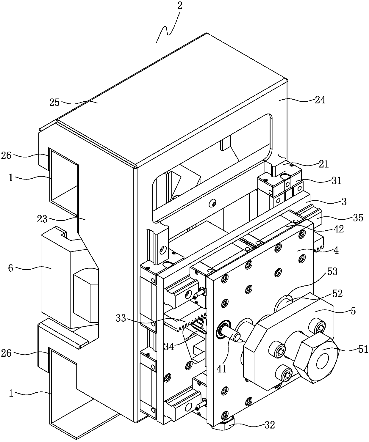
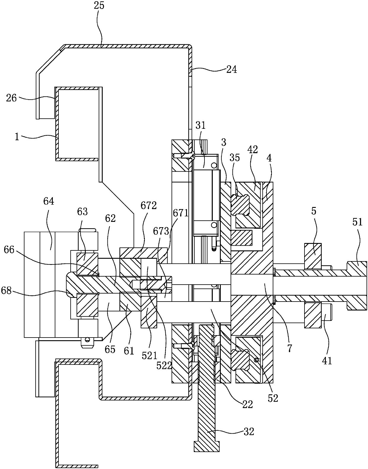
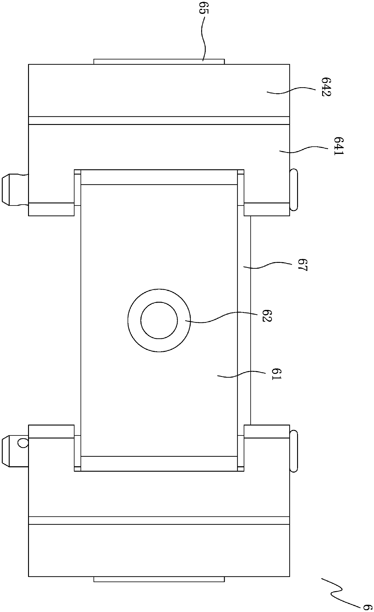
[0024] like Figure 1 to Figure 5 As shown, the transformer positioning device is used to locate the transformer to the corresponding position of the cabinet, including the bracket 2 that can be fixed on the cabinet, the first main board 3 that can be moved up and down on the bracket 2 through the Y-axis moving mechanism, and the first main board 3 through the X The second main board 4 that can be horizontally moved on the first main board 3 by the axis moving mechanism, the third main board 5 that can be moved back and forth on the second main board 4 through the Z-axis moving mechanism, and the third main board 5 that is detachably arranged on the third main board 5 on the clamp 6 for clamping the transformer; the clamp 6 includes a base 61, a connecting rod 62 that can be moved back and forth on the base 61, a base plate 63 that is set on the connecting rod 62, and a base plate 63 that is rotatably set on the base plate Two claws 64 at both ends of 63, two stoppers 65 arran...


PUM


Abstract

The invention discloses a clamp. The clamp comprises a base, a connecting rod arranged on the base in a front-back moving mode, a base plate arranged on the connecting rod, two clamping jaws arrangedat the two ends of the base plate in a rotatable mode, two blocking pieces arranged at the two ends of the base so as to block the clamping jaws, wherein the connecting rod drives a substrate to movebackwards when the connecting rod moves backwards, and locking piece applies a reaction force to the clamping jaw to enable the two clamping jaws to move relative to each other so as to clamp the clamped object. According to the clamp, the clamped object can be clamped for a long time, the structure is simple, the operation is convenient, and the power requirement is low.

Description

technical field [0001] The invention relates to a clamp. Background technique [0002] In our daily work, we often need to carry heavy objects or install and position some parts. If manual handling or lifting is adopted, it will take a lot of effort. However, if a mechanical method is used, a clamp that can clamp heavy objects during operation is required, but in the prior art, clamps that can realize this function are usually complex in structure, inconvenient to operate, and require high power requirements . Contents of the invention [0003] The object of the present invention is to provide a clamp which can clamp the object to be clamped and has simple structure, convenient operation and low power requirement. [0004] The present invention is realized through the following technical solutions: [0005] A fixture, comprising a base, a connecting rod set on the base which can move back and forth, a base plate set on the connecting bar, two claws rotatably set at bot...

Claims


Application Information

Patent Timeline
Patent Type & Authority Applications(China)
IPC IPC(8): B25J15/02
CPCB25J15/0206
Inventor 杨志豪张国灿庄严沈谢林连和黄峰铭林向宇柯凤祥靳宇翔刘煌煌
Owner QUANZHOU POWER SUPPLY COMPANY OF STATE GRID FUJIAN ELECTRIC POWER
Why Eureka
Try Eureka