Composite roller mold with replaceable surface structure and manufacturing process thereof
A surface structure, composite roller technology, applied in the direction of household appliances, other household appliances, optical components, etc., can solve the problem of difficult to form optical plates, and achieve the effect of shortening the development cycle, production cost and difficulty.
- Summary
- Abstract
- Description
- Claims
- Application Information
AI Technical Summary
Problems solved by technology
Method used
Image

Examples
Embodiment 1
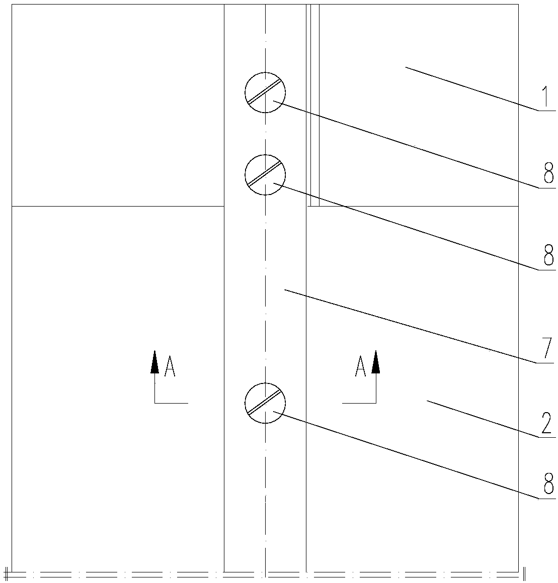
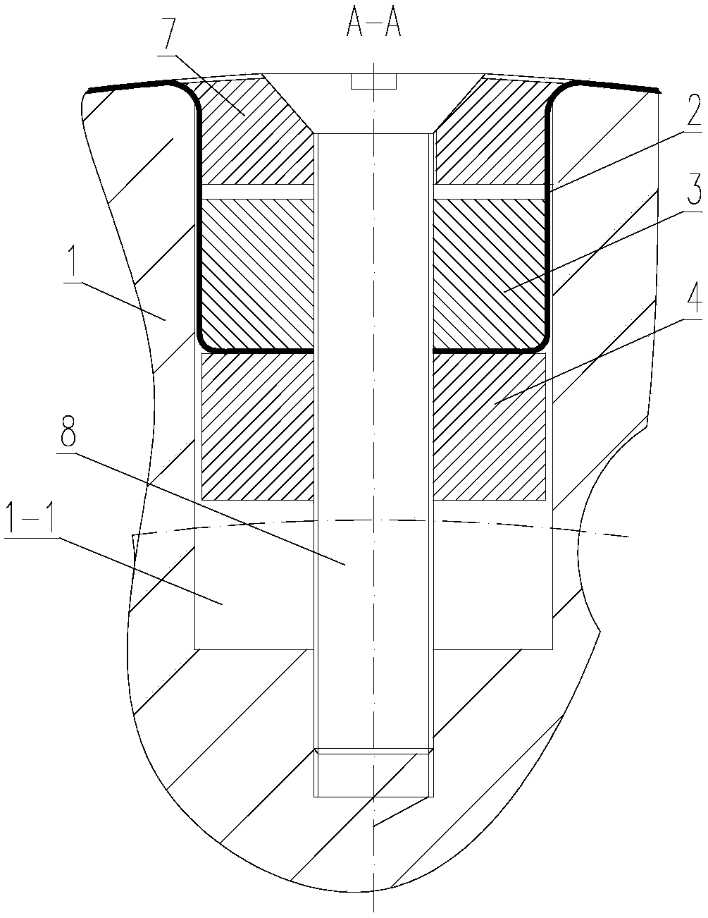
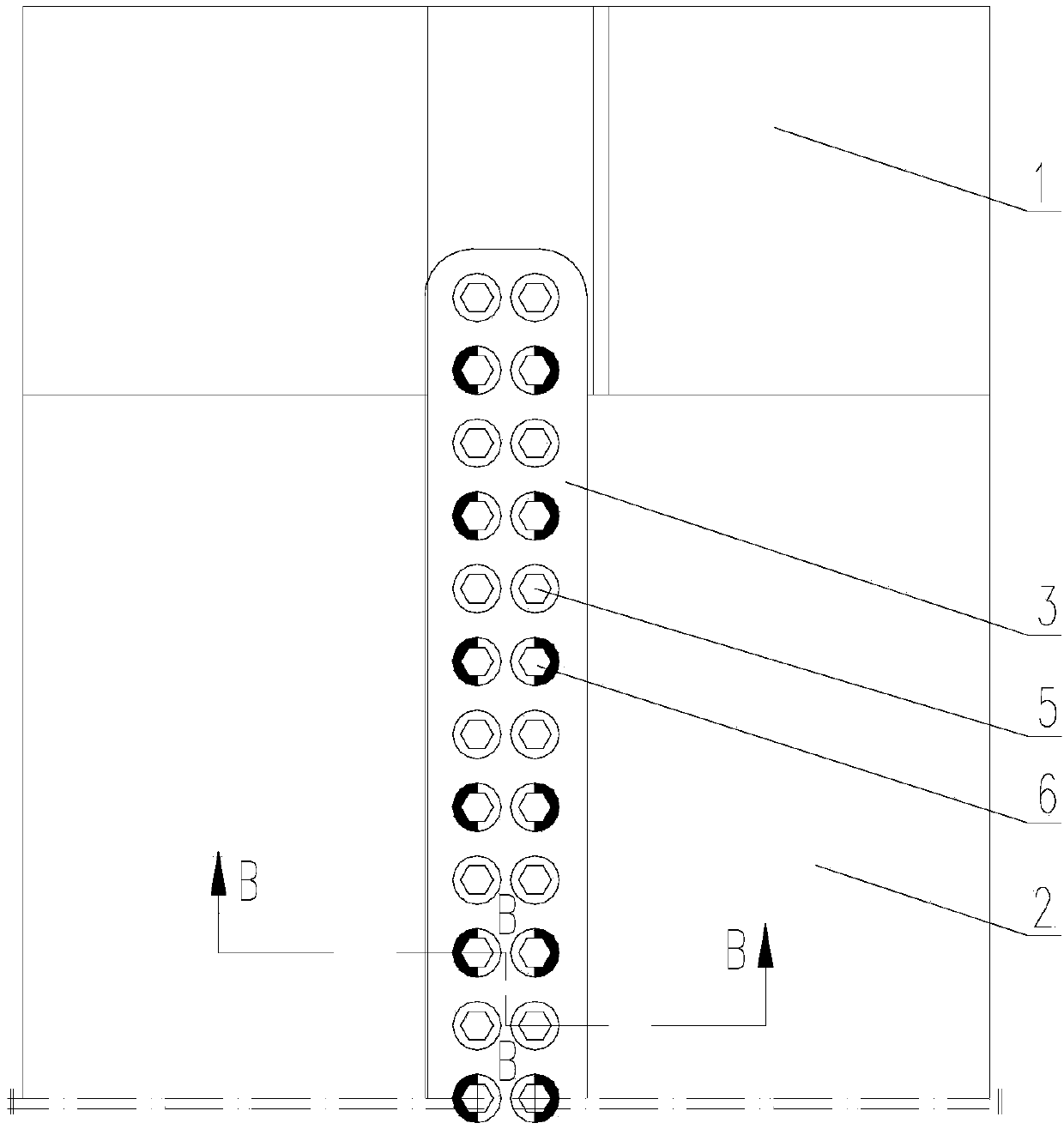
[0028] Such as Figure 1-5 As shown, a composite roller mold with a replaceable surface structure is used for embossing optical plates, including a roller body 1 and a metal belt 2 with an embossed structure on the outer surface. The outer peripheral surface of the roller body 1 is along its An installation groove 1-1 is provided in the axial direction, and the metal belt 2 is covered on the outer peripheral surface of the roller body 1. The head end and tail end of the metal belt 2 are located in the installation groove 1-1, and the installation groove 1-1 is formed The upper bead 3 and the lower bead 4 are arranged sequentially from the outside to the inside, the upper bead 3 and the lower bead 4 are matched with the installation groove 1-1, the head end and the tail end of the metal strip 2 are located between the upper bead 3 and the lower bead 4 Between the upper bead 3 and the lower bead 4, there is a locking screw 5, and the upper bead 3 is provided with an adjusting sc...
Embodiment 2
[0038] A manufacturing process of a replaceable composite roller mold with a surface structure in embodiment 1, comprising the following steps:
[0039] a, prepare the metal strip 2, and process an embossed structure on the outer surface of the metal strip 2;
[0040] b. Then mill out the installation groove 1-1 on the outer peripheral surface of the roller body 1 along its axial direction, and place the lower bead 4 and the upper bead 3 in the installation groove 1-1 from the inside to the outside;
[0041] c. Then wrap the metal strip 2 on the outer peripheral surface of the roller body 1, tighten the metal strip 2, and place the head end and tail end of the metal strip 2 between the upper bead 3 and the lower bead 4, and then pass the lock Tightening screw 5 locks the head end and tail end of metal strip 2 between the upper bead 3 and the lower bead 4;
[0042] d. Finally, pass the threaded end of the adjusting screw 6 through the upper bezel 3 and the lower bead 4 in sequ...
PUM
| Property | Measurement | Unit |
|---|---|---|
| Thickness | aaaaa | aaaaa |
Abstract
Description
Claims
Application Information
 - R&D
- Intellectual Property
- Life Sciences
- Materials
- Tech Scout
- Unparalleled Data Quality
- Higher Quality Content
- 60% Fewer Hallucinations
Browse by: Latest US Patents, China's latest patents, Technical Efficacy Thesaurus, Application Domain, Technology Topic, Popular Technical Reports.
© 2025 PatSnap. All rights reserved.Legal|Privacy policy|Modern Slavery Act Transparency Statement|Sitemap|About US| Contact US: help@patsnap.com