Screw metering equipment device

A metering equipment and screw-type technology, applied in the field of screw-type metering equipment, can solve the problems of high use and maintenance costs, accumulation, affecting the blanking effect of the blanking screw, etc., so as to improve the blanking effect and ensure the effect of automation.

Inactive Publication Date: 2018-05-18
沈佩军
View PDF0 Cites 1 Cited by
  • Summary
  • Abstract
  • Description
  • Claims
  • Application Information

AI Technical Summary

Problems solved by technology

The invention uses a servo motor to control the rotation of the feeding screw. Although the control effect of the servo motor is good, the servo motor is expensive and the cost of use and maintenance is high. Internal accumulation, thus affecting the feeding effect of the feeding screw

Method used


Image

  • Screw metering equipment device

Examples


Embodiment Construction

[0012] The present invention will be further described below in combination with the accompanying drawings and specific embodiments.

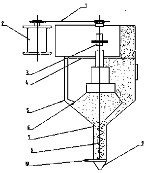
[0013] Such as figure 1 As shown, a screw-type metering device is mainly composed of a transmission belt 1, a motor 2, a battery clutch 3, a support 4, a hopper 5, an agitator 6, a conduit 7, a metering screw 8, a funnel 9 and a gate 10. The electric motor 2 is set on the left side of the electromagnetic clutch 3, the upper part of the motor 2 is connected with the transmission belt 1 above the electromagnetic clutch 3, the electromagnetic clutch 3 is set above the support 4, the support 4 is set above the hopper 5, and the hopper 5 is equipped with a stirring 6, directly below the hopper 5 is connected to the conduit 7, the conduit 7 is provided with a metering screw 8, the lower side of the conduit 7 is connected to the funnel 9, the connection between the funnel 9 and the conduit 7 is provided with a gate 10; the hopper 5 is provided with an...


PUM


Abstract

The invention discloses a screw metering equipment device. The screw metering equipment device mainly consists of a transmission belt, a motor, a battery clutch, a support, a hopper, a stirrer, a guide pipe, a metering screw, a funnel and a gate; the motor is arranged on the left side of an electromagnetic clutch; the upper side of the motor and the upper side of the electromagnetic clutch are connected through arrangement of the transmission belt; the electromagnetic clutch is arranged above the support; the support is arranged above the hopper; the stirrer is arranged in the hopper; the guide pipe is connected rightly below the hopper; the metering screw is arranged in the guide pipe; the lower side of the guide pipe is connected with the funnel; and the gate is arranged in the connectedplace of the funnel with the guide pipe. When the automation degree is guaranteed, the screw metering equipment device reduces the production and maintenance costs, and improves the unloading effect.

Description

technical field [0001] The invention belongs to the technical field of metering equipment, and in particular relates to a screw-type metering device. Background technique [0002] The screw metering device uses the screw feeder to complete the metering, that is, the volume measured by the cavity seat of the screw groove, in each packing cycle, the physical quantity transmitted by each rotation of the screw can be controlled by controlling the rotation speed of the screw. so as to be measured. It has a hopper, the two sides of the hopper are planes, the front is a stepped vertical semi-cylindrical surface, the rear is a semi-cylindrical surface whose axis and horizontal plane form an angle of 45°-70°, and the top is a stepped plane. There is a servo motor arranged on the lower step plane of the hopper, the motor shaft of the servo motor is coaxially connected with the feeding screw, and a material guide tube matched with the feeding screw is connected at the lower end of the...

Claims


Application Information

Patent Timeline
Patent Type & Authority Applications(China)
IPC IPC(8): B65B37/10B65B37/20
CPCB65B37/10B65B37/20
Inventor 沈佩军
Owner 沈佩军
Why Eureka
Try Eureka