
Automatic discharging device of material pulling frame

A technology of automatic unloading device and material frame, applied in vibrating conveyors, transportation and packaging, conveyors, etc., to achieve the effects of ensuring smooth operation, improving production efficiency, and improving use efficiency

Inactive Publication Date: 2018-05-18
芜湖尚唯汽车饰件有限公司
View PDF4 Cites 0 Cited by
  • Summary
  • Abstract
  • Description
  • Claims
  • Application Information

AI Technical Summary

Problems solved by technology

[0003] The technical problem to be solved in the present invention is that the existing pulling frame cannot realize the positioning and blanking well, and the process of fully unloading the material will easily lead to poor operation of the equipment and affect production efficiency

Method used


Image

  • Automatic discharging device of material pulling frame
  • Automatic discharging device of material pulling frame
  • Automatic discharging device of material pulling frame

Examples


Embodiment Construction

[0014] The preferred technical solutions of the present invention will be described in detail below in conjunction with the accompanying drawings.

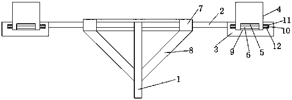
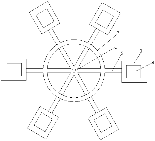
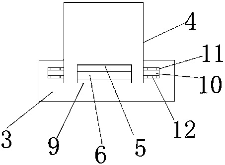
[0015] As shown in the figure, the automatic unloading device for the pulling frame of the present invention includes a rotating shaft 1, and a plurality of support rods 2 that diverge are evenly spaced around the upper end of the rotating shaft 1, and one end of each supporting rod 2 is rotatably connected to the rotating shaft 1. The other end of the support rod 2 is provided with a support base 3, a pull frame 4 is installed above the support base 3, a groove 5 is set at the bottom of the pull frame 4, and a vibration mechanism 6 is installed in the groove 5.

[0016] Further, a circular auxiliary support frame 7 is connected in the middle of a plurality of support rods 2, and an inclined support frame 8 is arranged below the circular auxiliary support frame 7. One end of the inclined support frame 8 is connected to the circular...


PUM


Abstract

The invention discloses an automatic discharging device of a material pulling frame. The automatic discharging device of the material pulling frame comprises a rotary shaft, wherein multiple divergingsupport rods are uniformly arranged on the periphery of the upper end of the rotary shaft at intervals; one end of each support rod is rotatably connected onto the rotary shaft; a support base is arranged on the other end parts of the support rods; the material pulling frame is arranged above the support base; a groove is formed in the bottom part of the material pulling frame; and a vibrating mechanism is arranged in the groove. According to the automatic discharging device of the material pulling frame provided by the invention, the rotary shaft sequentially rotates the material pulling frame on the end parts of the support rods to a blanking position for blanking, then the rotary shaft is rotated in place, and the support rods are rotated to rotate and inversely place the material pulling frame, so that materials in the material pulling frame are discharged; and in addition, the vibrating mechanism is arranged on the bottom part of the material pulling frame and can be used for vibrating and beating the material pulling frame, so that thorough discharging is ensured.

Description

technical field [0001] The invention relates to the technical field of mechanical equipment, in particular to an automatic unloading device for a pulling frame. Background technique [0002] In the process of using molds to manufacture automotive interiors, a pull frame can be used for blanking and unloading. In the material transportation link, a transmission mechanism is generally used for transmission, but most of the materials are placed in the pull frame, and the pull frame It needs to be arranged in sequence for conveying. During the conveying process, it is necessary to perform processes such as feeding, unloading or vibrating paving on the pulling frame, so the conveying of general materials needs to master the rhythm. For general conveyor belt or chain transmission, etc., the position of the pulling frame is not easy to grasp, which affects the loading of the pulling frame and the rhythm of the conveying mechanism. For the structure that fixes the pulling frame on ...

Claims


Application Information

Patent Timeline
IPC IPC(8): B65G47/74B65G27/16
CPCB65G47/74B65G27/16
Inventor 杜战军陈昊刘帅刘俊梅何红胜黄德福李嘉明
Owner 芜湖尚唯汽车饰件有限公司
Learn More