Disc brake with floating caliper

A technology of disc brake and floating caliper, which is applied in the direction of brake type, axial brake, brake parts, etc., and can solve the problems of high brake and brake pipeline manufacturing requirements, large friction plate consumption, and small friction plate area. and other problems, to achieve the effect of increasing the stability of the connection installation, increasing the installation area, and improving the positioning accuracy

Inactive Publication Date: 2018-05-18
方秀萍
View PDF0 Cites 1 Cited by
  • Summary
  • Abstract
  • Description
  • Claims
  • Application Information

AI Technical Summary

Problems solved by technology

The brake disc is made of alloy steel and fixed on the wheel, and rotates with the wheel. According to the structure of the caliper, the caliper disc brake can be divided into two types: fixed caliper disc type and floating caliper disc type. The disadvantages of disc brakes are: Because the friction plate directly acts on the disc, there is no automatic friction boosting effect, the braking efficiency is low, the manufacturing requirements for the brake and the brake pipeline are high, the wear of the friction plate is large, the cost is expensive, and due to friction The area of ​​the disc is small, and the working surface of the relative friction is also small. The wear limit thickness of the brake disc is 8mm. When the thickness is lower than this standard, new accessories should be replaced. When the thickness of the friction disc is less than 7mm, the friction disc must be replaced, and the left and right The wheels must be replaced in a complete set. If they are not replaced in time, it may cause a car accident. At the same time, when the floating caliper disc brake is braking, the brake caliper will have a certain displacement. The traditional way of using springs as the brake caliper is fixed. Displacement, but the performance is unstable, there is a certain inclination between the friction plate and the brake disc after the movement, the braking effect is poor, and the loss is faster

Method used


Image

  • Disc brake with floating caliper
  • Disc brake with floating caliper
  • Disc brake with floating caliper

Examples


Embodiment Construction

[0020] In order to further understand the invention content, characteristics and effects of the present invention, the following embodiments are listed below, and detailed descriptions are as follows in conjunction with the accompanying drawings.

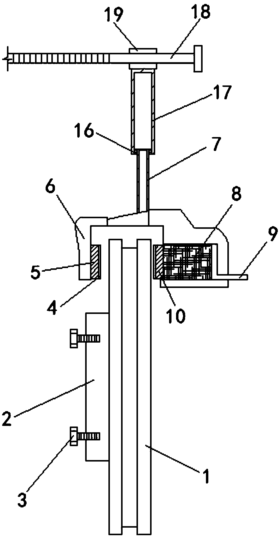
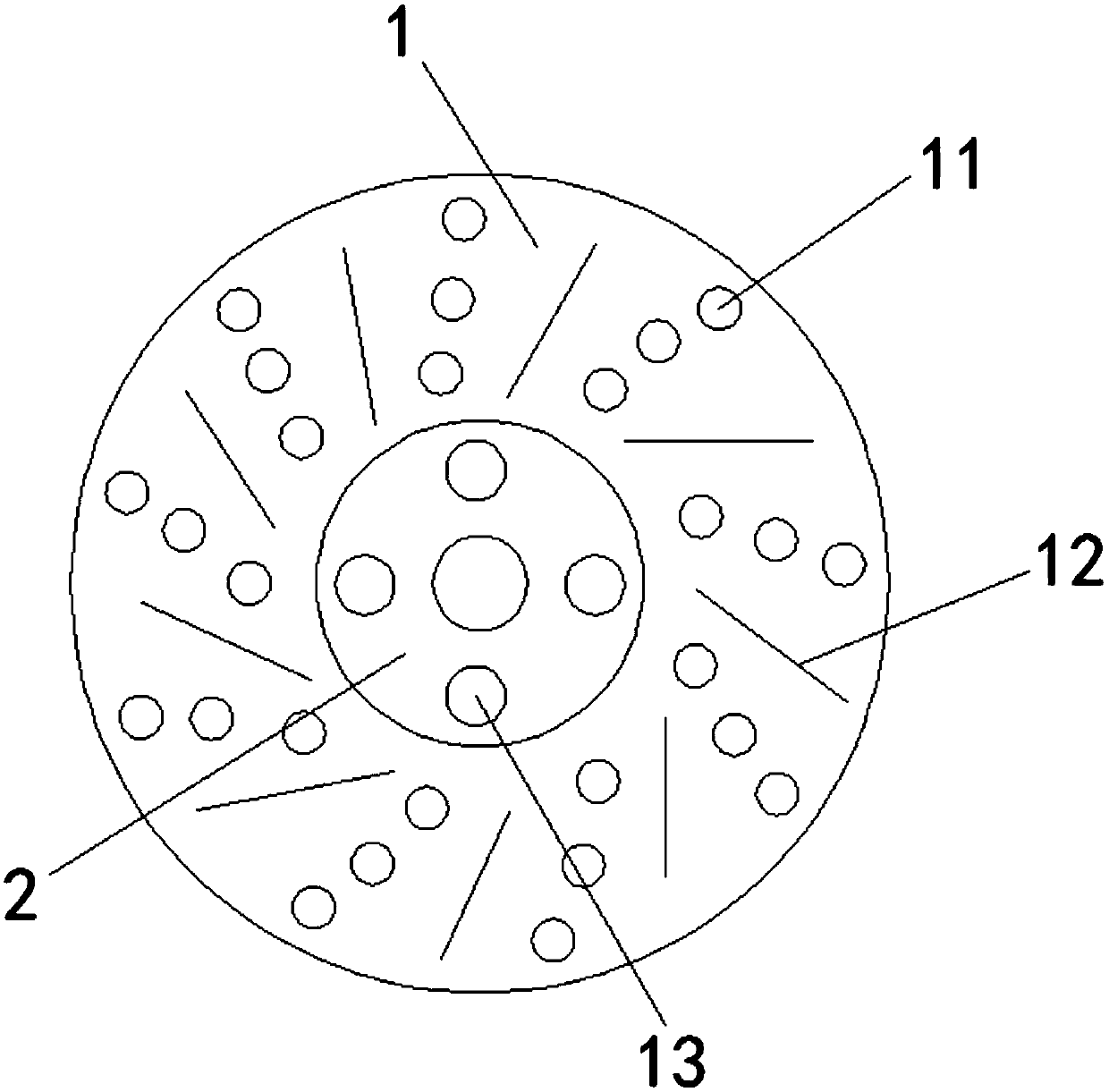
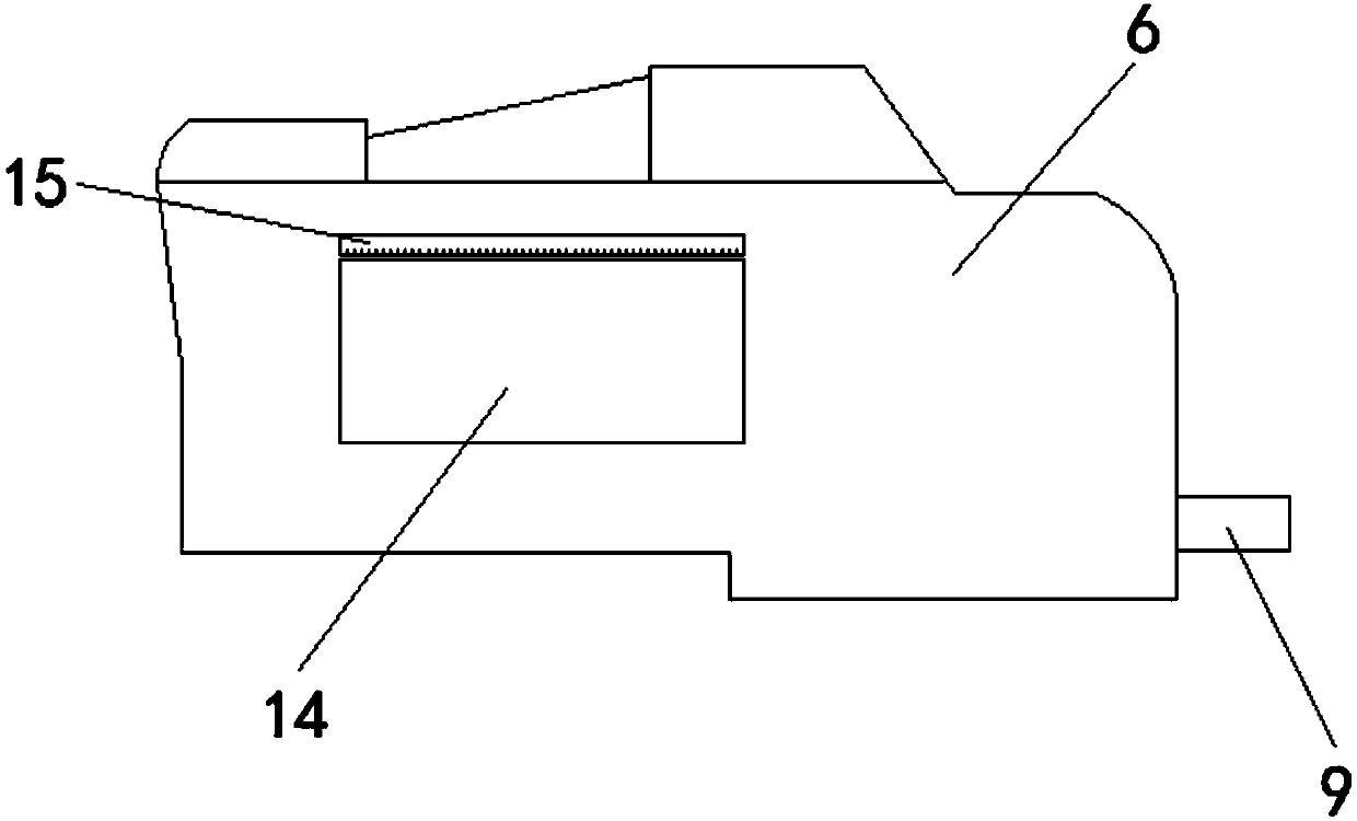
[0021] Combine below Figure 1-3 The floating caliper disc brake of the present invention is described in detail: a floating caliper disc brake includes a brake disc 1, a hub 2, a brake caliper 6, a piston 8 and an oil pipe 9, and the left side of the brake disc 1 is in the middle A wheel hub 2 is arranged on the position, and the wheel hub 2 is fixedly connected with the brake disc 1. A plurality of bolt holes 13 are arranged on the wheel hub 2, and bolts 3 are arranged in the bolt holes 13. The two sides of the brake disc 1 There are a number of scratches 12 arranged obliquely, and a number of through holes 11 are arranged between the scratches 12. The through holes 11 run through the brake disc 1, and a brake caliper 6 is arrange...


PUM

PropertyMeasurementUnit
Thicknessaaaaaaaaaa

Abstract

The invention relates to a disc brake with a floating caliper. The disc brake with the floating caliper includes a brake disc, a hub, a brake caliper, a piston and an oil tube, the hub is arranged atthe right center position of the left side of the brake disc, and the hub is fixedly connected with the brake disc and is provided with a plurality of bolt holes; and first bolts are arranged in the bolt holes, and two side surfaces of the brake disc are provided with a plurality of aslant arranged scratches. According to the disc brake with the floating caliper, positioning screws and guide ringsare arranged to fix the position of the brake caliper, the movement of the brake caliper is not affected while the position of the brake caliper is fixed, the performance is steady, and the brake caliper is not slant during moving; the brake effect is improved, the full contact of friction plates and the brake disc can be ensured, the loss is slowed, a connecting rod is arranged above the brake caliper and a sleeve is arranged above the connecting rod, and the connecting rod and the sleeve are slidably connected; and when the friction plates or the piston in the brake caliper is broke, the brake disc and the other devices do not need to be overall dismounted, and check and maintenance can be performed only need to take down the brake caliper.

Description

technical field [0001] The invention belongs to the technical field of brakes, in particular to a floating caliper disc brake. Background technique [0002] Disc brakes are also known as disc brakes. As the name suggests, they are named after their shape. It is controlled by hydraulic pressure, and its main components include brake disc, wheel cylinder, brake caliper, oil pipe and so on. The brake disc is made of alloy steel and fixed on the wheel, and rotates with the wheel. According to the structure of the caliper, the caliper disc brake can be divided into two types: fixed caliper disc type and floating caliper disc type. The disadvantages of disc brakes are: Because the friction plate directly acts on the disc, there is no automatic friction boosting effect, the braking efficiency is low, the manufacturing requirements for the brake and the brake pipeline are high, the wear of the friction plate is large, the cost is expensive, and due to friction The area of ​​the di...

Claims


Application Information

Patent Timeline
IPC IPC(8): F16D55/226F16D65/095F16D65/18F16D65/847F16D66/02F16D121/04
CPCF16D55/226F16D65/0037F16D65/095F16D65/18F16D65/847F16D66/02F16D2121/04
Inventor 方秀萍
Owner 方秀萍
Why Eureka
Try Eureka