
Capacitive voltage transformer transient response test device and test method thereof

A technology of voltage transformer and transient response, applied in measuring devices, instruments, measuring electrical variables, etc., can solve problems such as low test efficiency, unsafe test personnel, and no complete set of test equipment, etc., to achieve automatic and rapid measurement. , to achieve photoelectric isolation, to ensure the effect of safety

Inactive Publication Date: 2018-05-18
CHINA XD ELECTRIC CO LTD +1
View PDF5 Cites 3 Cited by
  • Summary
  • Abstract
  • Description
  • Claims
  • Application Information

AI Technical Summary

Problems solved by technology

[0004] In order to solve the problems in the existing capacitive voltage transformer test technology that there is no complete set of test equipment for the transient response test, resulting in low test efficiency and unguaranteed safety of the test personnel, a transient response of the capacitive voltage transformer is provided The test device and test method can realize the opening and closing control of the circuit breaker and the photoelectric isolation of the voltage measurement and the high-voltage test area during the transient response test, as well as the high-accuracy, automatic and rapid analysis of each short-circuit test data

Method used


Image

  • Capacitive voltage transformer transient response test device and test method thereof
  • Capacitive voltage transformer transient response test device and test method thereof
  • Capacitive voltage transformer transient response test device and test method thereof

Examples


Embodiment Construction

[0037] The present invention will be described in detail below in conjunction with the accompanying drawings and specific embodiments.

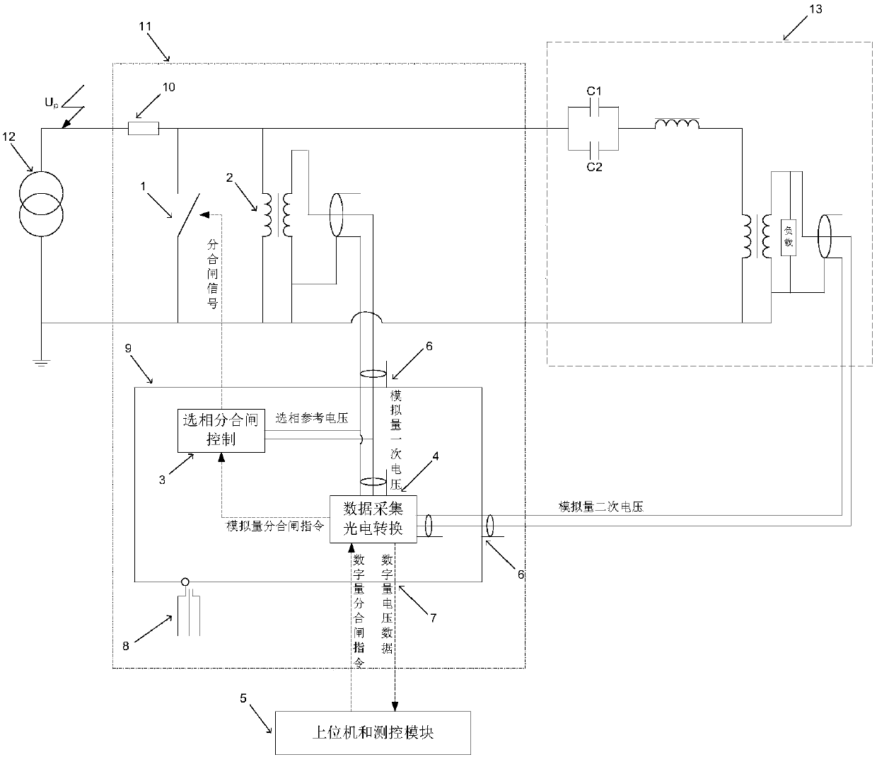
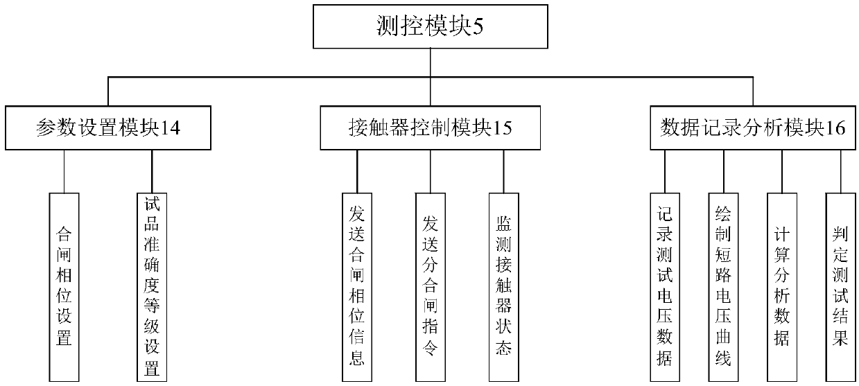
[0038] Such as figure 1 As shown, the capacitive voltage transformer transient response test device of the present invention includes a 35kV circuit breaker 1, a 35kV voltage transformer 2, a phase selection opening and closing controller 3, a data acquisition photoelectric conversion module 4, a host computer and a measurement and control module 5. Coaxial port 6, fiber optic port 7, power module 8, shielded chassis 9, movable base 11.

[0039] The circuit connection relation of the present invention is:

[0040] The high-voltage end of the test transformer 12 is connected to the protective resistor 10, one end of the 35kV circuit breaker 1 is connected to the protective resistor 10, and the other end is connected to the grounding end of the test transformer 12; one end of the capacitive voltage transformer 13 to be tested is connected to the...


PUM


Abstract

The invention provides a capacitive voltage transformer transient response test device and a test method thereof. The test device comprise a circuit breaker, a voltage transformer, a phase selection opening and closing controller, a data acquisition photoelectric conversion module, a host computer and a measurement and control module. The circuit breaker, the voltage transformer and a tested capacitive voltage transformer are all connected in parallel with a test transformer. The host computer and measurement and control module are in communication connection with the data acquisition photoelectric conversion module. The data acquisition photoelectric conversion module is in communication connection with the phase selection opening and closing controller. The phase selection opening and closing controller is in communication connection with the circuit breaker. The voltage transformer is connected with the data acquisition photoelectric conversion module and the phase selection openingand closing controller. The data acquisition photoelectric conversion module is connected with the tested capacitive voltage transformer. The test device realizes a full-automatic quick test and greatly improves the test efficiency. In addition, by means of photoelectric isolation, a tester can perform tests in a control room far away from a high-voltage area to ensure the safety.

Description

technical field [0001] The invention belongs to the field of capacitive voltage transformer tests, in particular to a transient response test device and a test method for a capacitive voltage transformer. Background technique [0002] The national standard for capacitive voltage transformers "GB / T 20840.5-2013 Supplementary Technical Requirements for Capacitive Voltage Transformers" specifies the transient response test: After the power supply between the high-voltage terminal A and the grounded low-voltage terminal N is short-circuited, The secondary voltage of the capacitor voltage transformer should be within the specified time T s internal decay to a specified value relative to the peak value of the voltage before the short circuit. The test can be carried out on a complete capacitive voltage transformer or on an equivalent circuit composed of actual capacitors, and the test should be performed at the actual primary voltage U p or equivalent circuit for U p ×C 1 / (C ...

Claims


Application Information

Patent Timeline
IPC IPC(8): G01R35/02
Inventor 杨忠州谢婷婷冯建华
Owner CHINA XD ELECTRIC CO LTD
Learn More