Servo steel supporting system axial force determining method taking maximum displacement as control target

A technology of maximum displacement and control target, applied in special data processing applications, instruments, electrical and digital data processing, etc., can solve problems such as single focus, unpredictable development of wall deformation, and lack of engineering forecasting ability.

Active Publication Date: 2018-05-18
SHANGHAI JIAO TONG UNIV
View PDF5 Cites 3 Cited by
  • Summary
  • Abstract
  • Description
  • Claims
  • Application Information

AI Technical Summary

Problems solved by technology

First, on-site real-time monitoring of deformation is the basis for regulation and lack of engineering prediction ability, so it is impossible to predict the development of wall deformation
Second, there are differences between the design of the servo system and the actual construction on site. This regulation can serve the actual...

Method used


Image

  • Servo steel supporting system axial force determining method taking maximum displacement as control target
  • Servo steel supporting system axial force determining method taking maximum displacement as control target
  • Servo steel supporting system axial force determining method taking maximum displacement as control target

Examples


Embodiment Construction

[0041] The specific embodiments of the present invention are given below in conjunction with the accompanying drawings, but the present invention is not limited to the following embodiments. Advantages and features of the present invention will be apparent from the following description and claims. It should be noted that all the drawings are in very simplified form and use imprecise ratios, which are only used for the purpose of conveniently and clearly assisting in describing the embodiments of the present invention.

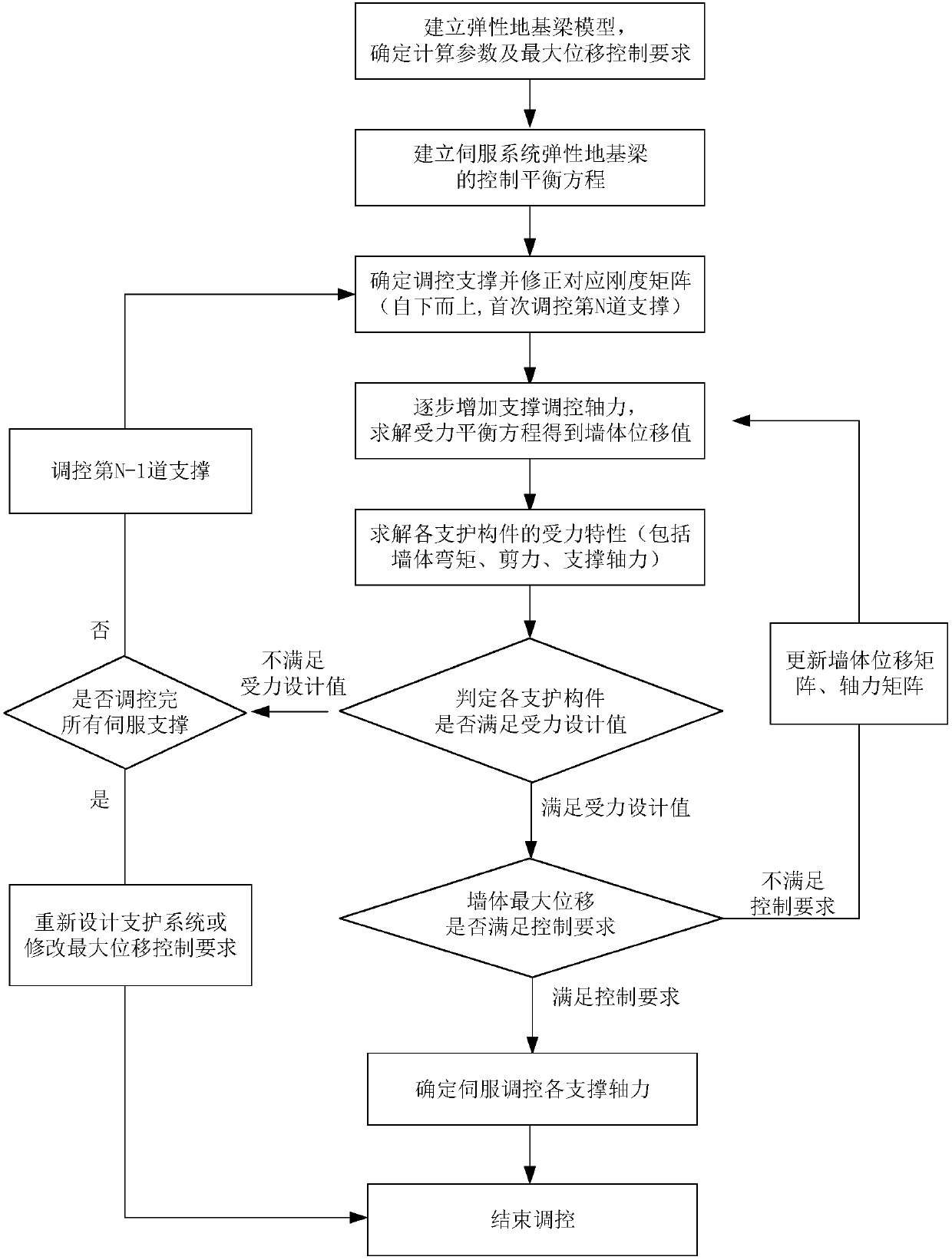
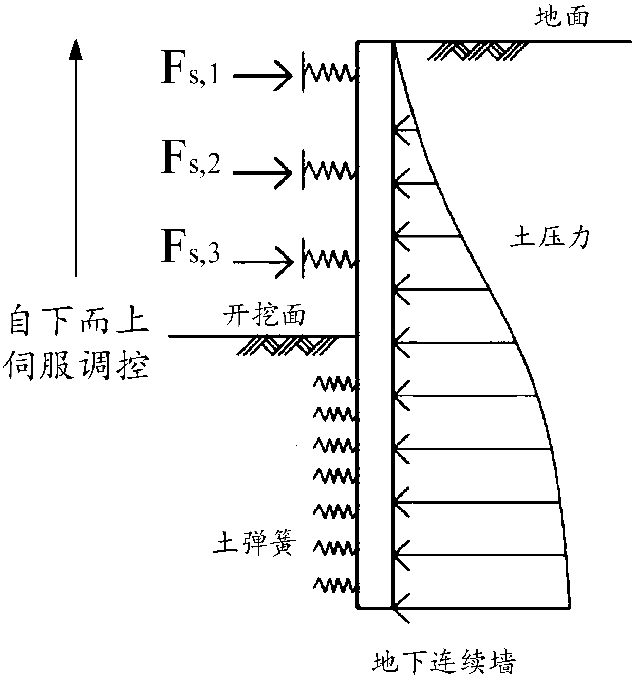
[0042]Please refer to figure 1 and figure 2 , figure 1 Shown is the calculation flow diagram of the preferred embodiment of the present invention, figure 2 Shown is a schematic diagram of the calculation model of the preferred embodiment of the present invention. The method for determining the axial force of the servo steel support system with the maximum displacement as the control target proposed by the present invention includes the following steps: ...


PUM


Abstract

The invention provides a servo steel supporting system axial force determining method taking maximum displacement as a control target. The method specifically includes following steps: (1), accordingto actual engineering, building an elastic foundation beam model, and determining related calculation parameters and maximum displacement control requirements; (2), establishing a control balance equation of a servo system elastic foundation beam; (3), determining a regulating support, and correcting a corresponding supporting rigidity matrix; (4), increasing regulating axial force value step by step, and solving a stress balance equation to acquire a corresponding wall displacement value; (5), calculating wall bending moment shear force and each supporting axial force value, and judging whether stress of each component meets a design value or not. On the basis of a servo system control balance equation, each boundary condition under control of axial force is judged through iterative calculation, a servo supporting control axial force determining method is provided, and a theoretical reference can be provided for design construction.

Description

technical field [0001] The invention relates to the field of force deformation calculation of servo steel support regulation in foundation pit engineering, and mainly relates to a method for determining the axial force of a servo steel support system with maximum displacement as the control target. Background technique [0002] With the rapid development of urban underground space, the requirements for the surrounding environment protection of foundation pit excavation are constantly increasing. Compared with the characteristics of passive force bearing of traditional supports, servo steel supports adopt the control method of actively applying axial force, which is more and more widely used in projects that require high deformation control of foundation pits. However, because the servo system has been popularized and used for a short period of time, the theoretical research on its control methods is insufficient, and the control methods adopted by the construction unit are r...

Claims


Application Information

Patent Timeline
IPC IPC(8): G06F17/50
CPCG06F30/13G06F30/23G06F2111/10G06F2119/06
Inventor 李明广黄彪陈锦剑高亿文侯永茂王建华
Owner SHANGHAI JIAO TONG UNIV
Why Eureka
Try Eureka