Displacement control valve for variable displacement compressor

Active Publication Date: 2009-04-30
EAGLE INDS +1
View PDF6 Cites 34 Cited by
  • Summary
  • Abstract
  • Description
  • Claims
  • Application Information

AI Technical Summary

Benefits of technology

[0007]It is an object of the present invention to provide a displacement control valve that shortens the time requir

Problems solved by technology

When the variable displacement compressor is activated in a state in which liquefied refrigerant is collected in the control pressure chamber, if the displacement control valve keep the cross-sectional area of the regulation passage in a small state, the liquefied refrigerant cannot be readily released from the control pressure chamber to the su

Method used


Image

  • Displacement control valve for variable displacement compressor
  • Displacement control valve for variable displacement compressor
  • Displacement control valve for variable displacement compressor

Examples


Embodiment Construction

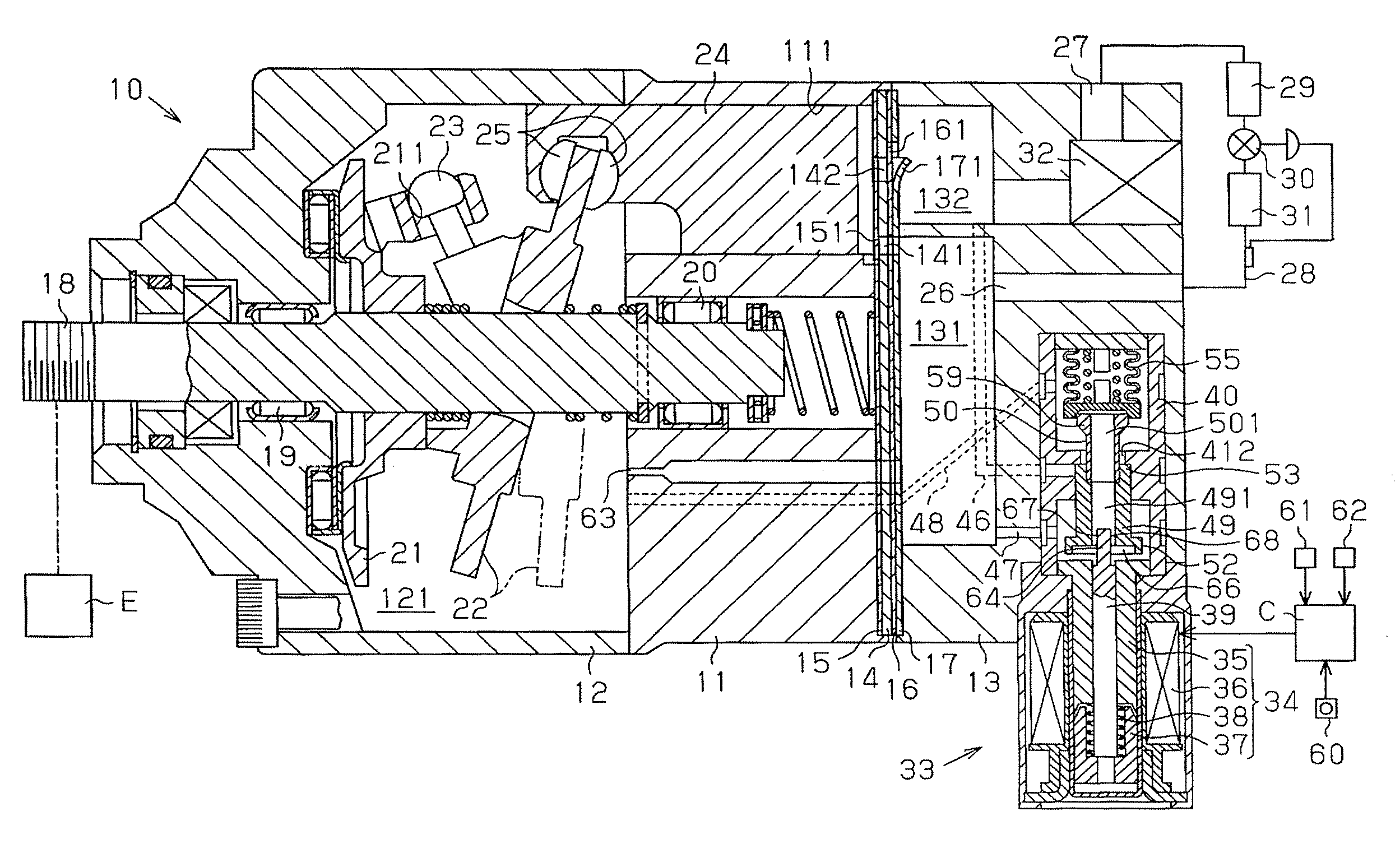
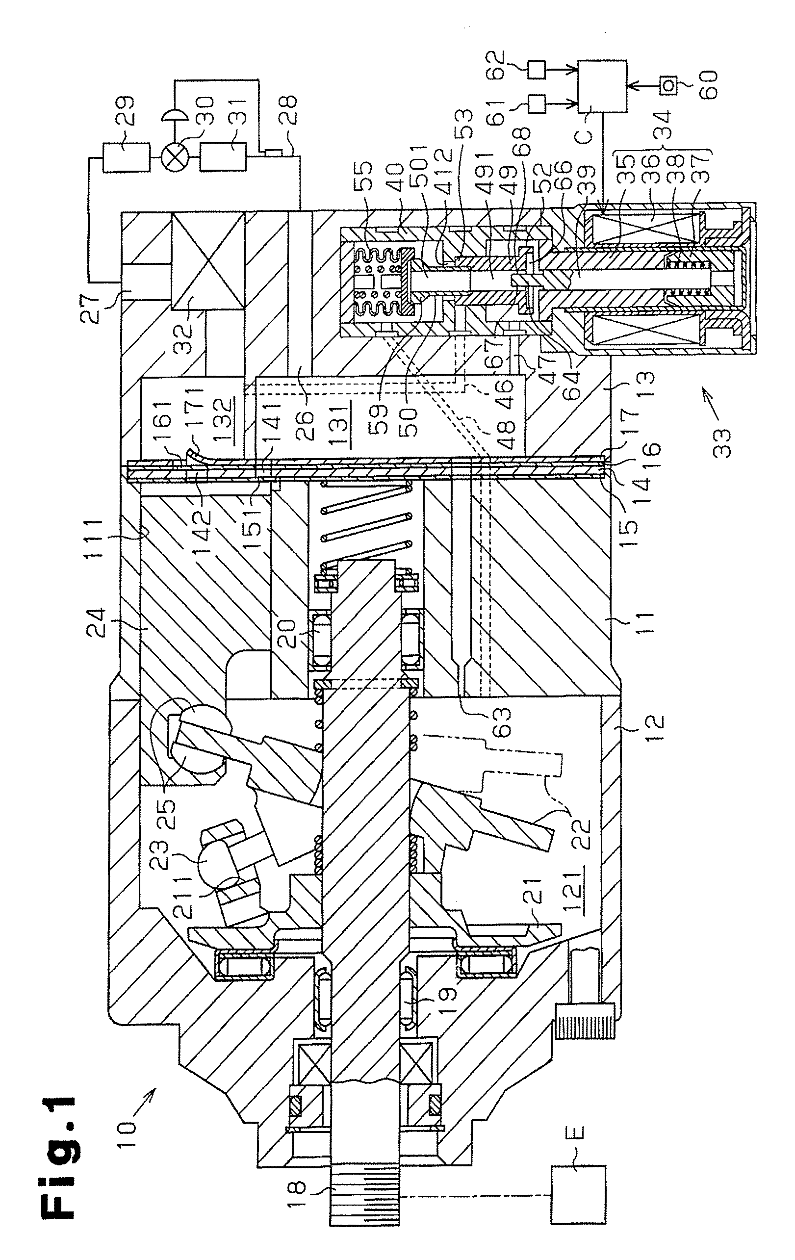
[0024]A first embodiment of a clutchless-type variable displacement compressor according to the present invention will now be discussed with reference to FIGS. 1 to 5.

[0025]As shown in FIG. 1, the housing of a variable displacement compressor 10 includes a cylinder block 11, a front housing member 12, and a rear housing member 13. The front housing member 12 is secured to the front end of the cylinder block 11, and the rear housing member 13 is secured to the rear end of the cylinder block 11 with a valve plate 14, valve flap plates 15 and 16, and a retainer plate 17 arranged in between. The cylinder block 11, the front housing member 12, and the rear housing member 13 form the housing of the compressor 10.

[0026]The front housing member 12 and the cylinder block 11 define a control pressure chamber 121. The front housing member 12 and the cylinder block 11 rotatably support a rotary shaft 18 with radial bearings 19 and 20. The rotary shaft 18, which protrudes out of the control pres...


PUM


Abstract

A displacement control valve for a variable displacement compressor. The displacement control valve includes a drive force transmission body, a pressure sensitive chamber, an internal passage, and a valve body. The valve body includes an annular seal which is contactable with a valve seat surface facing toward the first valve body. The drive force transmission body includes a drive rod and a valve body structure having a shaft passage and forming the first valve body. The drive rod is fitted to the shaft passage and coupled to the valve body structure so as to form a gap passage between an outer surface of the drive rod and a wall surface of the shaft passage. The internal passage includes a recess arranged radially inward from the annular seal, the shaft passage, and the gap passage. The gap passage is in direct communication with the recess.

Description

BACKGROUND OF THE INVENTION[0001]The present invention relates to a displacement control valve for a variable displacement compressor that adjusts the pressure in a control pressure chamber by supplying refrigerant from a discharge pressure region to the control pressure chamber and releases refrigerant from the control pressure chamber to a suction pressure region so as to control the compressor displacement in accordance with the pressure adjustment of the control pressure chamber.[0002]In a variable displacement compressor that includes a control pressure chamber accommodating a swash plate with a variable inclination angle, the inclination angle of the swash plate decreases as the pressure of a control pressure chamber becomes high and increases as the pressure of the control pressure chamber becomes low. When the inclination angle of the swash plate becomes small, the stroke of a piston becomes small and the displacement of the compressor decreases. When the inclination angle o...

Claims


Application Information

Patent Timeline
IPC IPC(8): F16K31/02
CPCF04B27/1804F04B2027/1854F04B2027/1827F04B2027/1813F04B27/1018F04B27/1081F04B49/22F05B2210/12F05B2210/14F16F1/04Y10S417/00
Inventor UMEMURA, SATOSHIHIROSE, TATSUYAHASHIMOTO, YUJIUEMURA, NORIOCHO, RYOSUKESHIRAFUJI, KEIGO
Owner EAGLE INDS
Why Eureka
Try Eureka